Always check unit before applying power (see Sections 8-2 thru 8-11).
TM-246193 Page 53Invision 352 MPa
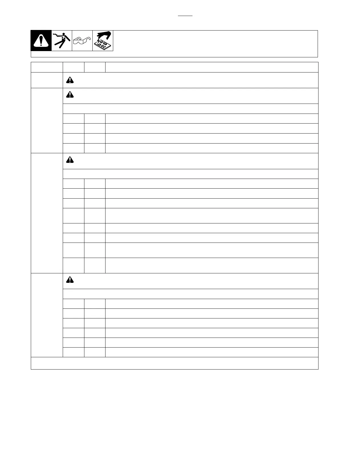
8-24. Power Interconnect Board PC2 Test Point Values
PC2 Voltage Readings
a) Tolerance − ±10% unless specified
b) Reference − to circuit common
(lead 42) unless noted
Receptacle Pin Type Value
RC1
! Do not measure − high voltage present.
RC2
! High voltage present. Voltages on this receptacle can exceed 900 volts DC from chassis (GND).
NOTE: All pins on this receptacle are referenced to the primary − Bus
1 Output Primary (+) bus; regulated to 940 volts DC with respect to primary (−) bus
2 Not Used
3 Not Used
4 Output Primary (+) rectifier; rectified primary line volts
RC3
! High voltage present. Voltages on this receptacle can exceed 900 volts DC from chassis (GND).
NOTE: All pins on this receptacle are referenced to the primary − Bus
1 Do not measure − Boost IGBT gate drive signal return
2 Input Do not measure − Boost IGBT gate drive signal
3 Output Do not measure − Boost inductor current feedback
4 Input −12 volts DC; regulated with respect to primary (−) bus, −12 volts DC power to boost inductor current
sensor
5 Precom Circuit common referenced to primary (−) bus
6 Precom Circuit common referenced to primary (−) bus
7 Input Precharge relay coil return; 0 volts DC = relay contacts open, −12 volts DC = relay contacts closed with
respect to primary (−) bus
8 Input +15 volts DC; regulated with respect to primary (−) bus, +15 volts DC power to boost inductor current
sensor
RC6
! High voltage present. Voltages on this receptacle can exceed 900 volts DC from chassis (GND).
NOTE: All pins on this receptacle are referenced to the primary − Bus
1 Snubber resistor1; input boost snubber, located in resistor module mounted to primary heat sink
2 Not Used
3 Snubber resistor2; inverter snubber, located in resistor module mounted to primary heat sink
4 Snubber resistor1; input boost snubber, located in resistor module mounted to primary heat sink
5 Not Used
6 Snubber resistor2; inverter snubber, located in resistor module mounted to primary heat sink
No testing required for remaining plugs and receptacles.

 Loading...