Always check unit before applying power (see Sections 8-2 thru 8-11).
TM-246193 Page 64 Invision 352 MPa
Section 8-32. Front Panel/Display Board PC3 Test Point Values (Continued)
Receptacle Pin Type Value
RC50 A Output 23 volts AC RMS at 10 amps; 14−pin remote accessory power
B Input Remote output enable; 0 volts AC = weld output off, 23 volts AC RMS = weld output on
C Output Output signal to remote command reference; +10 volts DC
D GND Remote command reference signal common
E Input Input signal from remote command; 0 to 10 volts DC, +13.5 volts DC when not connected to remote com-
mand from accessory
F Output Current feedback; 1 volt DC per 100 amperes of weld output
G GND 14−pin remote accessory power return
H Output Voltage feedback; 1 volt DC per 10 volts DC of weld output
I* Output 115 volts AC RMS at 2 amps; 14−pin remote accessory power
J* Input Remote output enable; 0 volts AC = weld output off, 115 volts AC RMS = weld output on
K Chassis Power source chassis
L Input Wirefeed command. 0 to +10 volts DC from synergic capable wire feeder
M Input Prior to MA370426A not used. Effective with MA370426A Remote Process Select. When connected to
Remote Process Select capable single wirefeeder; Mig = 3.5 volts DC, Pulse = 2.5 volts DC. When con-
nected to Remote Process Select capable dual wirefeeder; left side Mig = 5.5 volts DC, left side Pulse =
4.5 volts DC, right side Mig = 7.5 volts DC, right side Pulse = 6.5 volts DC
N Input Wire feed speed common
No testing required for remaining plugs and receptacles.
* 115 volts AC not available at RC50 eff w/ME224001U.
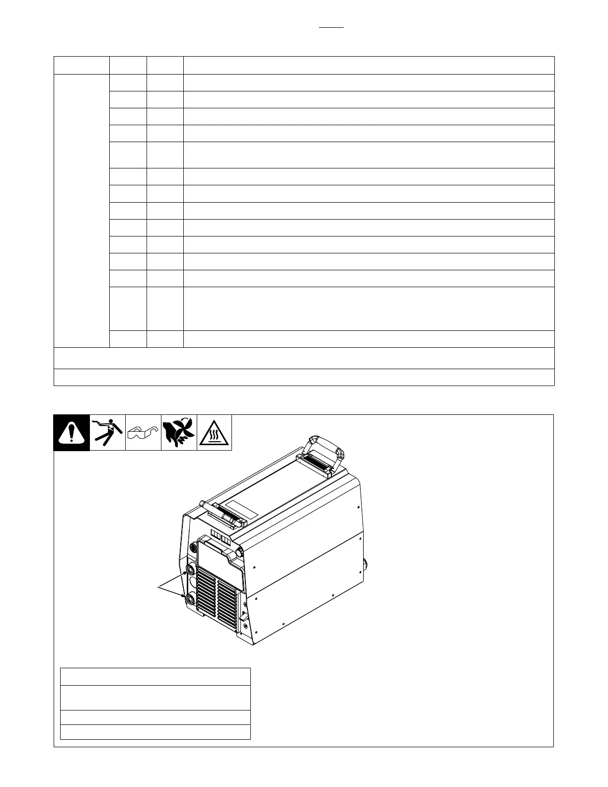
8-33. Checking Unit Output After Servicing
1 Weld Output Terminals
Check open-circuit voltage be-
tween terminals according to Sec-
tion 8-18 (voltage V-12)
If correct voltage is not present,
repeat troubleshooting procedures.
Perform a load bank test to en-
sure welding generator oper-
ates properly after servicing.
Be sure load bank is capable of
handling the rated output of the
welding generator being tested
(see load bank Owner’s Manu-
al).
The load bank will simulate a
weld load and the electrical de-
mand on the unit. See Specifi-
cations section for rated load.
If unit does not perform at rated
load, repeat troubleshooting
procedures.
Complete pre-operational checks.
Reinstall cover and side panels.
1
Check Unit Static 2018-12 - 803691-E
Pre-Operational Checks
Check labels; replace labels that are unreadable or
damaged (see Parts List).
Clean weld output terminals. Tighten connections.
Clean outside of entire unit.

 Loading...