TABLE OF CONTENTS
SECTION 1 − SAFETY PRECAUTIONS FOR SERVICING 1........................................
1-1. Symbol Usage 1.......................................................................
1-2. Servicing Hazards 1....................................................................
1-3. California Proposition 65 Warnings 2......................................................
1-4. EMF Information 2.....................................................................
SECTION 2 − DEFINITIONS 3..................................................................
2-1. Manufacturer Safety Symbols And Definitions 3.............................................
2-2. Miscellaneous Symbols And Definitions 5..................................................
SECTION 3 − SPECIFICATIONS 6..............................................................
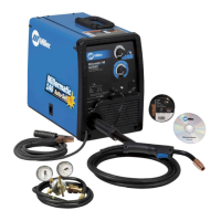
3-1. Features And Benefits 6................................................................
3-2. Arc Controls 6.........................................................................
3-3. Serial Number And Rating Label Location 6................................................
3-4. Software Licensing Agreement 6.........................................................
3-5. Information About Default Weld Parameters And Settings 6...................................
3-6. Unit Specifications 6....................................................................
3-7. Dimensions And Weight 7...............................................................
3-8. Environmental Specifications 7...........................................................
3-9. Duty Cycle And Overheating 8...........................................................
3-10. Static Output Characteristics 8...........................................................
SECTION 4 − INSTALLATION 9................................................................
4-1. Selecting A Location 9..................................................................
4-2. Selecting Cable Sizes* 10................................................................
4-3. Weld Output Terminals 10................................................................
4-4. Remote 14 Receptacle Information 11......................................................
4-5. Optional 115 Volts AC Duplex Receptacle And Supplementary Protectors 11.....................
4-6. Electrical Service Guide 12...............................................................
4-7. Connecting 1-Phase Input Power 14.......................................................
4-8. Connecting 3-Phase Input Power 16.......................................................
SECTION 5 − GENERAL OPERATION 18.........................................................
5-1. Front Panel 18..........................................................................
5-2. Configuration Option Menu 19.............................................................
5-3. Factory Reset Procedure 20..............................................................
SECTION 6 − GMAW/GMAW-P/FCAW OPERATION 21.............................................
6-1. Typical Connection For Remote Control Feeder GMAW/GMAW-P/FCAW Process 21..............
6-2. MIG Welding Mode - GMAW/FCAW Process 22..............................................
6-3. MIG - Wire and Gas Selection Table 23.....................................................
6-4. Pulsed MIG Welding Mode - GMAW-P Process 24...........................................
6-5. Pulsed MIG - Wire and Gas Selection Table 25..............................................
6-6. Remote Process Select 26...............................................................
SECTION 7 − THEORY OF OPERATION 28.......................................................
 Loading...