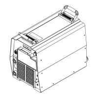
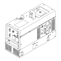
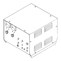
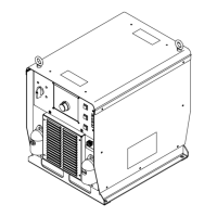
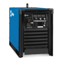
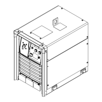
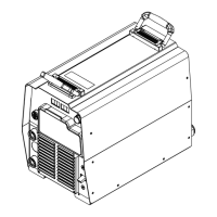
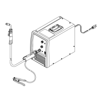
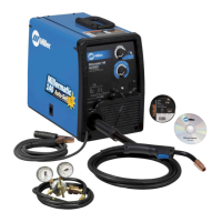
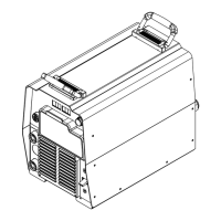
Always check unit before applying power (see Sections 8-2 thru 8-11).
TM-246193 Page 40 Invision 352 MPa
8-15. Troubleshooting Table
! Before connecting welding equipment to input (primary) power for servicing, be sure the input-power circuit protection is correct
for the welding equipment. Connect equipment to a dedicated circuit sized and fused for the rated output and duty cycle of the
welding equipment you are servicing. See the Electrical Service Guide section in this manual and National Electrical Code (NEC)
article 630, Electric Welders.
! Remove earth grounded wrist strap before performing any checks or procedures with power applied to the machine.
Equipment serviced may need to meet additional requirements as specified in IEC60974−4, Arc Welding Equipment - Part 4: Periodic
Inspection and Testing.
See Section 8-18 for test points and values.
Use MILLER Testing Booklet (Part No. 150853) when servicing this unit.
See the Miller Extranet for service memos that may aid in the repair of this product.
Trouble Remedy
No weld output; unit completely
inoperative.
Place line disconnect switch in On position (see Section 4-7 or 4-8).
Check and replace line fuse(s), if necessary, or reset circuit breaker (see Sections 4-7 and 4-8).
Check for proper input power connections and check condition of power cord
(see Section 4-7 or 4-8).
Check continuity of Power switch S1 and replace if necessary (see Section 8-12).
Check control transformer T2 for signs of winding failure. Check continuity across windings, and
check for proper connections. Check secondary voltages. Replace T2 if necessary.
Check control board PC1 and connections, and replace if necessary (see Pre-Power Checks in Sec-
tions 8-21 thru 8-22, and also see Section 8-19).
Check power interconnect board PC2 and connections, and replace if necessary (see Pre-Power
Checks in Sections 8-25 thru 8-26, and also see Section 8-23).
Check front panel/display board PC3 and connections, and replace if necessary (see Section 8-31).
No weld output; meter display On. Unit overheated and HELP 3 or HELP 5 screen is displayed. Allow unit to cool with fan On
(see Section 8-16).
If a remote accessory is connected to remote 14 receptacle RC50:
Check accessory contact closure (continuity), and replace accessory if necessary.
Check accessory amperage control potentiometer resistance and connections,
and replace accessory if necessary.
Check input and output voltages of hall device HD1 (see Section 8-18). Replace HD1 if necessary.
Check control board PC1 and connections, and replace if necessary (see Pre-Power Checks in Sec-
tions 8-21 thru 8-22, and also see Section 8-19).
Check front panel/display board PC3 and connections, and replace if necessary (see Section 8-31).
Low weld output with no control. Check input and output voltages of hall device HD1 (see Section 8-18). Replace HD1 if necessary.
Check control board PC1 and connections, and replace if necessary (see Pre-Power Checks in Sec-
tions 8-21 thru 8-22, and also see Section 8-19).
Check front panel/display board PC3 and connections, and replace if necessary (see Section 8-31).
Maximum weld output with no control. Check input and output voltages of hall device HD1 (see Section 8-18). Replace HD1 if necessary.
Check control board PC1 and connections, and replace if necessary (see Pre-Power Checks in Sec-
tions 8-21 thru 8-22, and also see Section 8-19).
Check front panel/display board PC3 and connections, and replace if necessary (see Section 8-31).
No weld output; Unit displays
HELP 25.
Unit exceeded duty cycle. Leave power on so fan cools unit. If HELP 25 does not clear after 15 minutes
with power on, check current feedback on HD1. Replace HD1 if necessary.
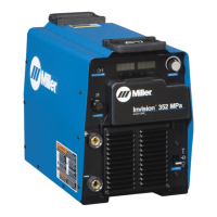
 Loading...
