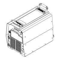
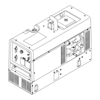
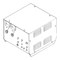
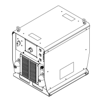
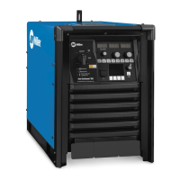
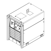
Always check unit before applying power (see Sections 8-2 thru 8-11).
TM-246193 Page 41Invision 352 MPa
Trouble Remedy
Limited output and low open circuit
voltage (OCV).
Check for proper input and output connections
If a remote accessory is connected to remote 14 receptacle RC50:
Check accessory contact closure (continuity), and replace accessory if necessary.
Check accessory amperage control potentiometer resistance and connections,
and replace accessory if necessary.
Check input and output voltages of hall device HD1 (see Section 8-18). Replace HD1 if necessary.
Check control board PC1 and connections, and replace if necessary (see Pre-Power Checks in Sec-
tions 8-21 thru 8-22, and also see Section 8-19).
Check front panel/display board PC3 and connections, and replace if necessary (see Section 8-31).
Erratic or improper weld output. Use proper size and type of weld cable (see Section 4-2).
Clean and tighten all weld connections.
Check for proper input and output connections.
Replace electrode.
If a remote accessory is connected to remote 14 receptacle RC50:
Check all remote accessory connections (proper pin/socket alignment).
Check accessory amperage control potentiometer resistance and connections,
and replace if necessary.
Check input and output voltages of hall device HD1 (see Section 8-18). Replace HD1 if necessary.
Check control board PC1 and connections, and replace if necessary (see Pre-Power Checks in Sec-
tions 8-21 thru 8-22, and also see Section 8-19).
Check front panel/display board PC3 and connections, and replace if necessary (see Section 8-31).
Arc length is too long, no restrictions
are present, and a reduction of the arc
length setting is unresponsive.
Perform factory reset function (see Section 8-17).
The full voltage range of 10V to 38V is
unattainable.
Undesired changes in the arc.
The wire feeder and power source dis-
plays do not agree. For example, one
display shows arc length while the oth-
er display shows volts.
No 24 volt AC output at Remote 14 re-
ceptacle RC50.
Reset supplementary protector CB2 if necessary (see Section 4-5).
Check receptacle wiring and connections.
No 115 volt AC output at Remote 14
receptacle RC50 or optional duplex re-
ceptacle RC2.
Reset supplementary protector CB1 if necessary (see Section 4-5).
Eff w/ME224001U, 115 volts AC is not available at RC50.
Check receptacle wiring and connections.
Fan motor does not run after approxi-
mately four minutes of operation at
rated load.
Check and clear blocked fan blade
Check receptacle wiring and connections. Check thermistors RT-1 and RT-2 (see Section 8-18).
Fan motor FM1 starts and meters display HELP-2 when RT-1 or RT-2 is disconnected from PC1.
When RT-1 or RT-2 is reconnected, the meter displays change but the fan continues to run (see Sec-
tion 8-16).
Check fan motor FM (see Section 8-18) and replace fan motor if necessary.
 Loading...
