TM-246193 Page 28 Invision 352 MPa
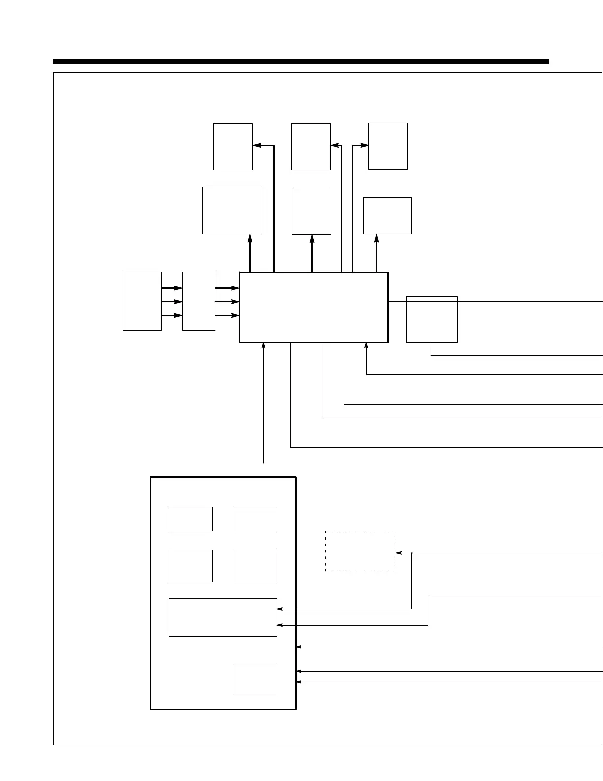
SECTION 7 − THEORY OF OPERATION
Power Interconnect Board
PC2
Remote 14-Pin Receptacle
RC50
Arc
Control
Voltmeter
V
Ammeter
A
Front Panel And Display Board PC3
Voltage/
Amperage
Adjust
Weld
Process
Control
Positive (+) Output Voltage Feedback
Negative (−) Output Voltage Feedback
Ribbon Cable
24 VAC
115 VAC
Boost Gate Signal
Optional
Auxiliary Power
115 VAC
Receptacle
Input Boost Inductor
Current Feedback
Input Rectifier Voltage
Bus Voltage
Current
Transformer
CT1
4
56
78
9
123
10
17
18
18
19 20
21
22
23
♦
Inverter
Module
Mod2
Bus
Capacitors
C12, C13
Boost
Snubber
Inductor
L2
Snubber
Resistor
Module
RM1
Boost
Input
Inductor
L1
Input
Pre-Regulator
Module
Mod1
Power
Switch
S1
1 Phase
or
3 Phase
Input
Power
115 Volts AC at RC50 was removed
Eff w/ME224001U.

 Loading...