Always check unit before applying power (see Sections 8-2 thru 8-11).
TM-246193 Page 49Invision 352 MPa
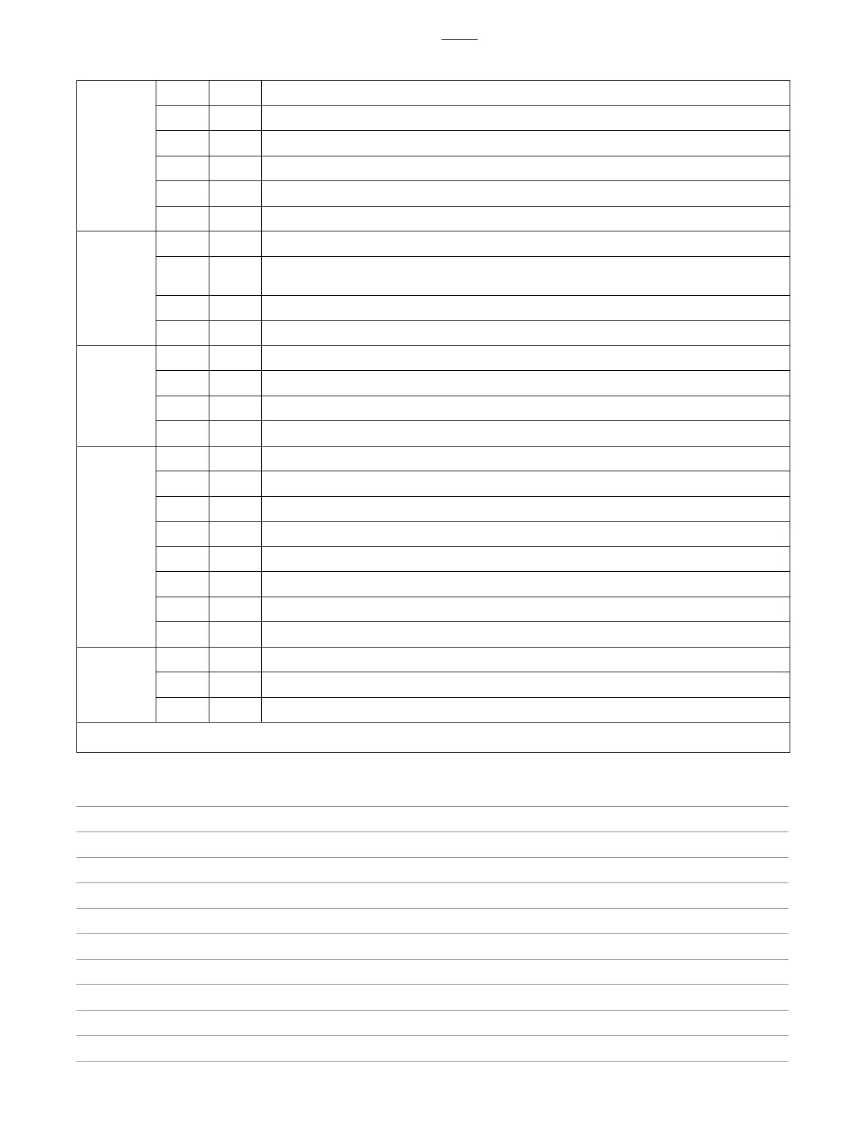
Section 8-20. Control Board PC1 Test Point Values (Continued)
RC9 1 Output Do not measure − Test point, used to test board only
2 Output Do not measure − Test point, used to test board only
3 Input Do not measure − Weld output current sensor signal
4 Output +15 volts DC power to current sensor
5 Output −15 volts DC power to current sensor
6 GND Weld output current sensor signal common
RC10 1 Output 115 volts AC RMS with respect to GND; power feed to fan
2 Output Fan power return; measure with respect to RC10−1, 115 volts AC RMS = fan on, less than 20 volts AC
RMS = fan off
3 Output Do not measure − Test point, used to test board only
4 Output Do not measure − Test point, used to test board only
RC11 1 Not Used
2 Not Used
3 Not Used
4 Not Used
RC12 1 Not Used
2 Input 34 volts AC RMS; measure with respect to RC12 pin 4, power supply used to create +24/−24 volts DC
3 Chassis Power source chassis; circuit common (GND) on this pin bonded to chassis thru wire
4 Input 34 volts AC RMS; measure with respect to RC12 pin 2, power supply used to create +24/−24 volts DC
5 Not Used
6 Input Center tap of 34 volt AC connected to circuit common (GND) on board
7 Not Used
8 Not Used
RC13 1 Input 115 volts AC RMS
2 Not Used
3 GND Circuit common referenced to chassis
No testing required for remaining plugs and receptacles.
Notes

 Loading...