OM-291865 Page 12
SECTION 4 – SPECIFICATIONS
4-1. Serial Number And Rating Label Location
The serial number and rating information for this product is located on the back of the work table, above the input power connections. Use rating
label to determine input power requirements and/or rated output. For future reference, write serial number in space provided on cover of this
manual.
4-2. Software Licensing Agreement
The End User License Agreement and any third-party notices and terms and conditions pertaining to third-party software can be found at
https://www.millerwelds.com/eula and are incorporated by reference herein.
4-3. Information About Default Weld Parameters And Settings
NOTICE – Each welding application is unique. Although certain Miller Electric products are designed to determine and default to certain typical
welding parameters and settings based upon specific and relatively limited application variables input by the end user, such default settings are
for reference purposes only; and final weld results can be affected by other variables and application-specific circumstances. The appropriate-
ness of all parameters and settings should be evaluated and modified by the end user as necessary based upon application-specific require-
ments. The end user is solely responsible for selection and coordination of appropriate equipment, adoption or adjustment of default weld
parameters and settings, and ultimate quality and durability of all resultant welds. Miller Electric expressly disclaims any and all implied warran-
ties including any implied warranty of fitness for a particular purpose.
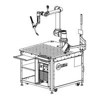
4-4. Cobot System Specifications
Input Power 3-phase 240-575 VAC
Cobot requires separate 110 VAC input
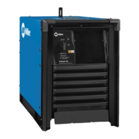
Welder Specifications Auto Continuum 350
350A at 31.5 VDC at 100% duty cycle
System Dimensions (HxWxD) 84 in. x 48 in. x 52 in. (2134 mm x 1219 mm x 1321 mm)
Payload capacity with feet 1500 lb (680 kg)
(Assuming evenly spread across table)
Payload capacity with casters 750 lb (340 kg)
(Assuming evenly spread across table)
Load Height 37 in. (940 mm)
System Weight 1700 lb (771 kg)
Torch Specifications Tregaskiss CA3 Torch
350A Air Cooled
Table Specifications 5/8 in. diameter holes on 2 in. grid spacing 48 x 48 in (1219 x 1219 mm).
Table is nitride hardened and reversible