OM-291865 Page 23
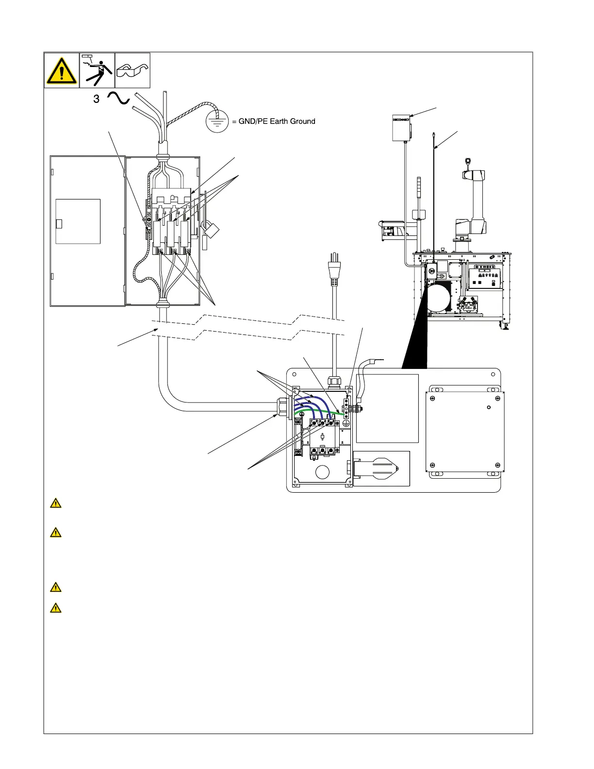
5-5. Connecting 3-Phase Input Power
8
7
9
10
1
6
3
5
4
2
230-575 VAC, 3 Phase
120 VAC, 1 Phase
Installation must meet all National
and Local Codes— have only quali-
fied persons make this installation.
Disconnect and lockout/tagout input
power before connecting input con-
ductors from unit. Follow estab-
lished procedures regarding the
installation and removal of lockout/
tagout devices.
Make input power connections to
the cobot system first.
Always connect green or green/yel-
low conductor to supply grounding
terminal first, and never to a line
terminal.
See rating label on unit and check input volt-
age available at site.
1 Input Power Conductors (Customer Sup-
plied Cord)
Select size and length of conductors using
Electrical Service Guide. Conductors must
comply with national, state, and local electri-
cal codes.
Cobot System Input Power Connections
2 Strain Relief Installed On Disconnect OR
Strain Relief (Customer Supplied)
Install strain relief of proper size for unit and
conductors. Route conductors (cord)
through strain relief. Tighten strain relief.
3 Cobot System Grounding Terminal
4 Green Or Green/Yellow Grounding
Conductor
Connect green or green/yellow grounding
conductor to machine grounding terminal
first.
5 Cobot System Line Terminals
6 Input Conductors (L1, L2, And L3)
Connect input conductors L1, L2, and L3 to
cobot system line terminals.
Disconnect Device Input Power
Connections
7 Disconnect Device (switch shown in the
OFF position)
8 Disconnect Device Grounding Terminal
9 Disconnect Device Line Terminals
Connect green or green/yellow grounding
conductor to disconnect device grounding
terminal first.
Connect input conductors L1, L2, and L3 to
disconnect device line terminals.
10 Over-Current Protection
Select type and size of over-current protec-
tion using Electrical Service Guide (fused
disconnect switch shown).
Close and secure door on disconnect de-
vice. Follow established lockout/tagout pro-
cedures to put unit in service.