Complete Parts List is available at www.MillerWelds.com
OM-262506 Page 26
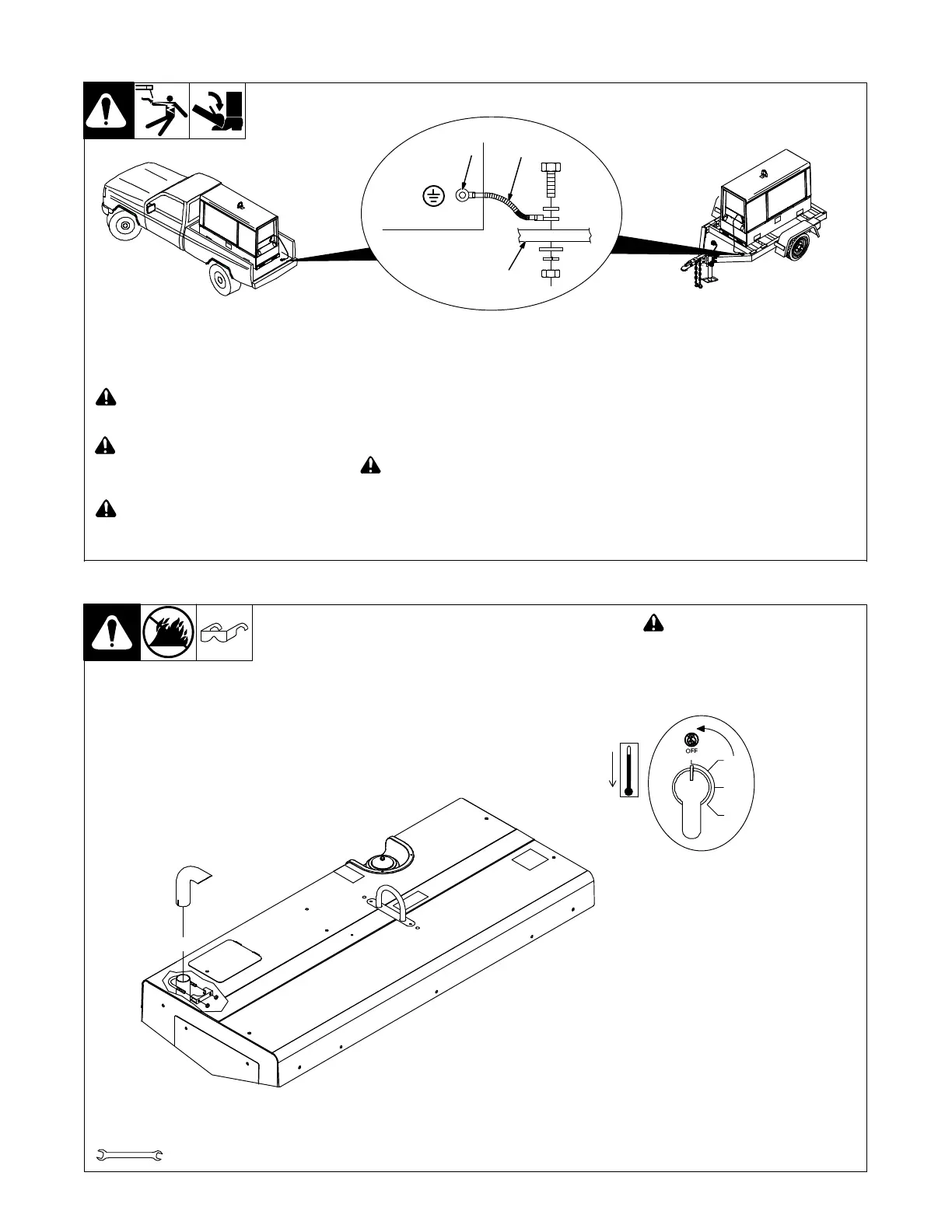
! Always ground generator frame to
vehicle frame to prevent electric
shock and static electricity hazards.
! Also see AWS Safety & Health Fact
Sheet No. 29, Grounding of Portable
And Vehicle Mounted Welding Gen-
erators.
! Bed liners, shipping skids, and
some running gear insulate the
welder/generator from the vehicle
frame. Always connect a ground
wire from the generator equipment
grounding terminal to bare metal on
the vehicle frame as shown.
! Use GFCI protection when operat-
ing auxiliary equipment. If unit does
not have GFCI receptacles, use
GFCI-protected extension cord. Do
not use GFCI receptacles to power
life support equipment.
1 Equipment Grounding Terminal (On
Front Panel)
2 Grounding Cable (Not Supplied)
3 Metal Vehicle Frame
Connect cable from equipment ground
terminal to metal vehicle frame. Use #8
AWG or larger insulated copper wire.
Electrically bond generator frame to ve-
hicle frame by metal-to-metal contact.
-2. Grounding Generator To Truck Or Trailer Frame
rot_grnd2 2014−11 − 800 652-D
1
3
2
GND/PE
5-3. Installing Exhaust Pipe
1/2 in.
Tools Needed:
! Stop engine and let cool.
Point exhaust pipe in desired di-
rection but always away from front
panel and direction of travel.
Exhaust Pipe3 2010−04 / Ref 803 582






 To Next Page