Complete Parts List is available at www.MillerWelds.com
OM-262506 Page 52
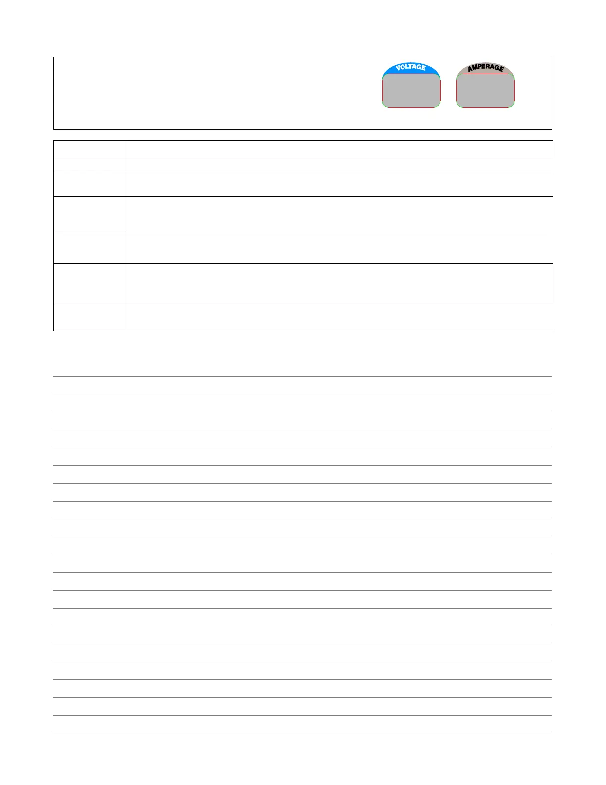
8-12. Voltmeter/Ammeter Help Displays
Display Example
HL.P
15
Use the Voltmeter/Ammeter help displays to diagnose and correct fault conditions.
When a help code is displayed normally weld output has stopped but generator
power output may be okay.
To reset help displays, stop unit and then restart. See below to reset Help 25 display.
Display Code Description
HL.P 15 Weld output was temporarily reduced due to engine power limit exceeded. Help code clears after 5 seconds.
HL.P 20 Indicates a failure of meter display module PC2, or the wiring between PC2 and main control module PC1. If this display is
shown, have Factory Authorized Service Agent check PC1, PC2, and the wiring between PC1 and PC2.
HL.P 21 Indicates thermal protector TP1 on stabilizer Z1 has opened (Z1 overheated) or thermistor TH1 on the main rectifier heat sink
has failed. If this display is shown, have, allow unit to cool and reduce duty cycle. If unit does not reset after cooling, have Facto-
ry Authorized Service Agent check TH1, and the wiring between TH1 and PC1.
HL.P 22 Indicates the rectifier heat sink has overheated. If this display is shown, check generator cooling system and/or reduce duty
cycle. Keep engine access door closed when running to maintain proper cooling air flow past rectifier. Allow unit to cool before
restarting. If problem continues, have Factory Authorized Service Agent check unit.
HL.P 25 Indicates a remote device connected to Remote Receptacle RC14 may be faulty. Help 25 is also displayed whenever a remote
device has been connected to RC14 and then disconnected. Clear fault by stopping and restarting the unit or by turning Pro-
cess/Contactor switch to another position. If problem continues, have Factory Authorized Service Agent check the remote de-
vice, filter board PC6, and main control module PC1.
HL.P 96 Indicates a failure of communication to the WCC module inside the unit. If this appears on the display, check connections to
WCC module. If connections are secure, WCC module needs to be replaced; Contact Factory Authorized Service Agent.
Notes
 Loading...