Complete Parts List is available at www.MillerWelds.com
OM-262506 Page 42
SECTION 7 − OPERATING AUXILIARY EQUIPMENT
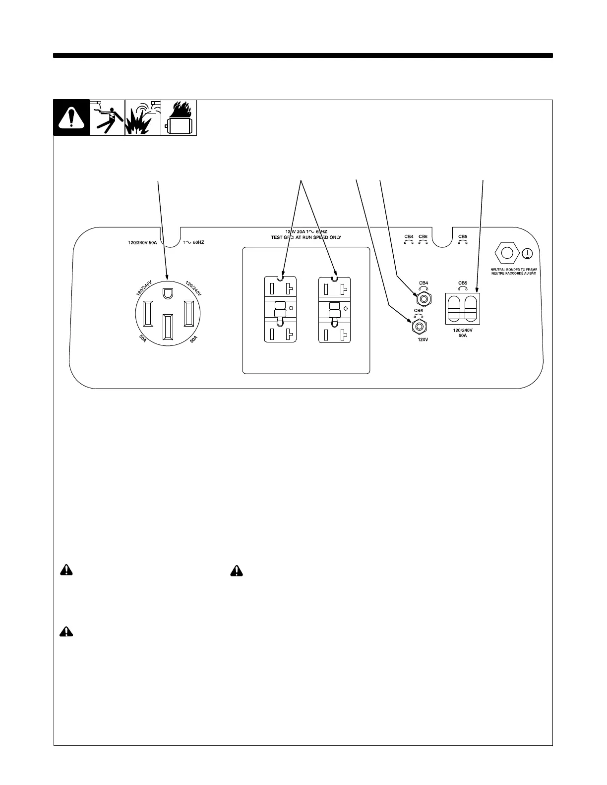
7-1. Generator Power Receptacles
263 481-A
! Use GFCI protection when operat-
ing auxiliary equipment. If unit does
not have GFCI receptacles, use
GFCI-protected extension cord. Do
not use GFCI receptacle to power
life support equipment.
! Unplug power cord before attempt-
ing to service accessories or tools.
1 120 V 20 A AC GFCI Receptacles
GFCI1 And GFCI2
GFCI1 and GFCI2 supply 60 Hz sing-
le-phase power at weld/power speed. See
Section 7-3 for GFCI information and for re-
setting and testing procedures.
Maximum output from these receptacles is
2.4 kVA/kW.
! Test GFCI monthly. See Section 7-3
for GFCI information and for reset-
ting and testing procedures.
2 240 V 50 A AC Receptacle RC11
RC11 supplies 60 Hz single-phase power
at weld/power speed. Maximum output
from RC11 is 10 kVA/kW.
3 Supplementary Protector CB4
4 Supplementary Protector CB6
5 Supplementary Protector CB5
CB4 protects GFCI2 and CB6 protects
GFCI1 from overload. If a supplementary
protector opens, the receptacle does not
work. Press button to reset.
Supplementary protector CB5 protects re-
ceptacles and the generator winding from
overload. If CB5 opens, the receptacles do
not work. Place CB5 switch in On position
to reset circuit breaker.
If a supplementary protector continues
to open, contact Factory Authorized
Service Agent.
Generator power decreases as weld
output increases.
Combined output of all receptacles is limit-
ed to the 10 kVA/kw rating of the generator.
EXAMPLE: If 15 A is drawn from each 120
V receptacle , only 26 A is available at the
240 V receptacle:
2 x (120 V x 15 A) + (240 V x 26 A) =
10.0 kVA/kW
1
2
3
4
5
 Loading...