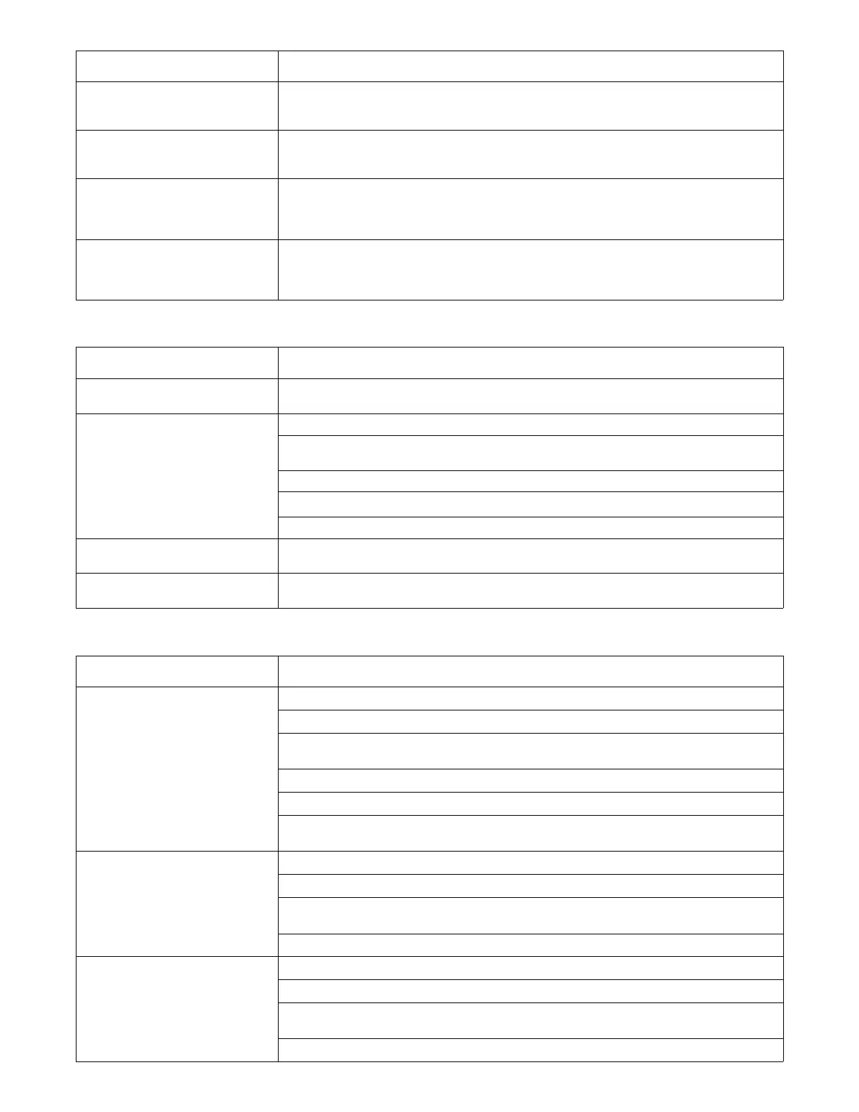
Complete Parts List is available at www.MillerWelds.com
OM-262506 Page 54
Trouble Remedy
Smart Feeder displays PoL Err. This is a Polarity Error. Ensure the positive (+) stud on the power source is connected to the electrode
stud on the Smart Feeder and the negative (−) stud on the power source is connected to the work stud
on the Smart Feeder.
The welder/generator or Smart Feeder
displays Help15.
Indicates that the output demand has exceeded the engine horsepower, causing the engine RPM to drop
below a specified level for a significant time. This code displays for 5 seconds before clearing on its own.
The output remains enabled when this code is active, but is reduced to prevent the engine from stalling.
Smart Feeder weld output fails while
welding (the Smart Feeder may show
H15 or completely reset).
Check the voltmeter display on the engine drive to see if HLP15 is displayed within 5 seconds of the weld
failure. HLP15 indicates that the power output demand of the engine has been exceeded. This can be
caused by excessive auxiliary power loads, engine wetstacking, or reduced output from an engine that
is not yet warmed up.
HLP 15 code is displayed while carbon−
arc gouging.
HLP15 indicates that the power output demand of the engine drive has been exceeded. This can be
caused by excessive auxiliary power loads, engine wetstacking, or reduced output from an engine that
is not yet warmed up. Reduce the amperage if gouging in CC mode, or reducing tip−to−work distance if
gouging in CV mode.
B. Generator Power
Trouble Remedy
No generator power output at AC recep-
tacles; weld output okay.
Reset receptacle supplementary protectors (see Section 7-1 or 7-2).Check and reset GFCI receptacles
if necessary (see Section 7-3).
No generator power or weld output. Disconnect equipment from generator power receptacles during start-up.
Check fuse F1, and replace if open (see Section 8-10). Have Factory Authorized Service Agent check
field excitation circuit.
Reset supplementary protector CB3 (see Section 8-10).
Check Voltmeter/Ammeter help displays (see Section 8-12).
Have Factory Authorized Service Agent check brushes and slip rings, and field excitation circuit.
High output at generator power AC re-
ceptacles.
Have Factory Authorized Service Agent check field excitation circuit.
Low output at generator power AC re-
ceptacles.
Check fuse F1, and replace if open (see Section 8-10). If F1 is open, have Factory Authorized Service
Agent check the rotor.
C. Engine
Trouble Remedy
Engine will not crank. Check battery, and replace if necessary. It may be necessary to remove oil filter to replace battery.
Check battery connections and tighten if necessary.
Circuit breaker CB1 may be open. CB1 automatically resets when fault is corrected (see Section 8-10).
Have Factory Authorized Service Agent check engine wiring harness and components.
Reset supplementary protector CB2 (see Section 8-10).
Check engine wiring harness plug connections.
Have Factory Authorized Service Agent check Engine Control switch S1, Fuel/Hour gauge FUEL/HM,
and control relay CR2.
Engine cranks but does not start. Check fuel level.
Check battery and replace if necessary. Check engine charging system according to engine manual.
Have Factory Authorized Service Agent check control relay CR1, Fuel/Hour gauge FUEL/HM, fuel
solenoid FS1, and the fuel pump.
Air in fuel system. See engine manual.
Engine hard to start in cold weather. Use Preheat switch S4 (see Section 6-2).
Keep battery in good condition. Store battery in warm area off cold surface.
Use fuel formulated for cold weather (diesel fuel can gel in cold weather). Contact local fuel supplier for
fuel information.
Use correct grade oil for cold weather (see engine manual).






 To Next Page