T1 Service Manual 2-5
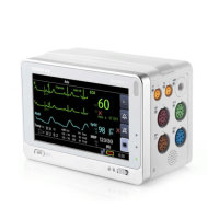
2.3.2 Right View
1. T1 handle multi-pin connector 2: connects the T1 handle and T1.
2. Infrared filter: used for communication between the T1 handle and external parameter module.
3. Contact: power input connector of the external parameter module.
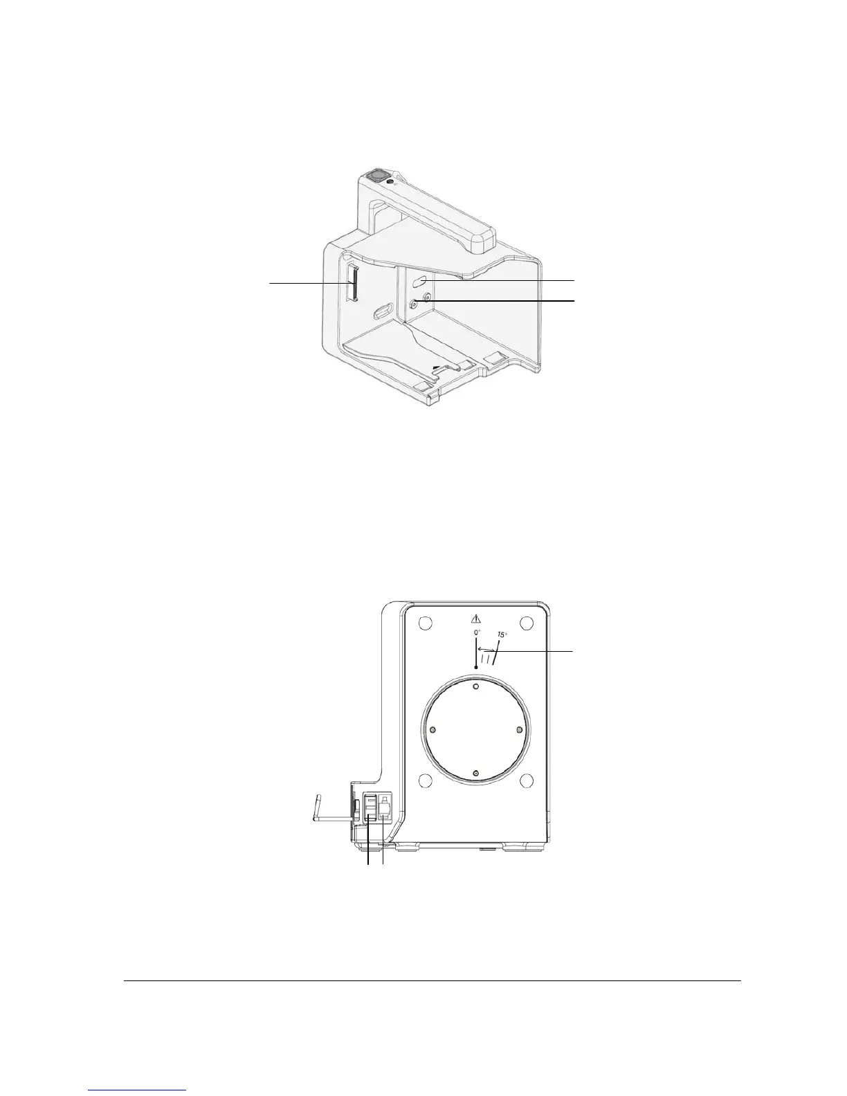
2.4 T1 Docking Station
2.4.1 Left View
1. Symbol: indicates the direction and angle that T1 docking station can rotate when T1 docking station is fixed onto a
transverse or a vertical rod.
2. USB connector: connects USB devices, including the USB drive, mouse and keyboard.
3. Network connector: a standard RJ45 connector that connects the patient monitor to the CMS or CIS.
1
2
3
1
3
2