AN-49-011 © 2023 Mini-Circuits
Rev. D | ECO-016581 | 25-Jan-2023 Page 12
4 - Hardware Setup
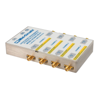
4.1. USB Control
Connect the attenuator to the computer using the provided USB cable or equivalent one, and then connect the required RF
connections.
Caution:
• The maximum allowed RF input for programmable attenuator models is reduced at low frequencies.
• Exceeding these values may damage the attenuator. Check the individual model datasheet and do not exceed
the specified limits.
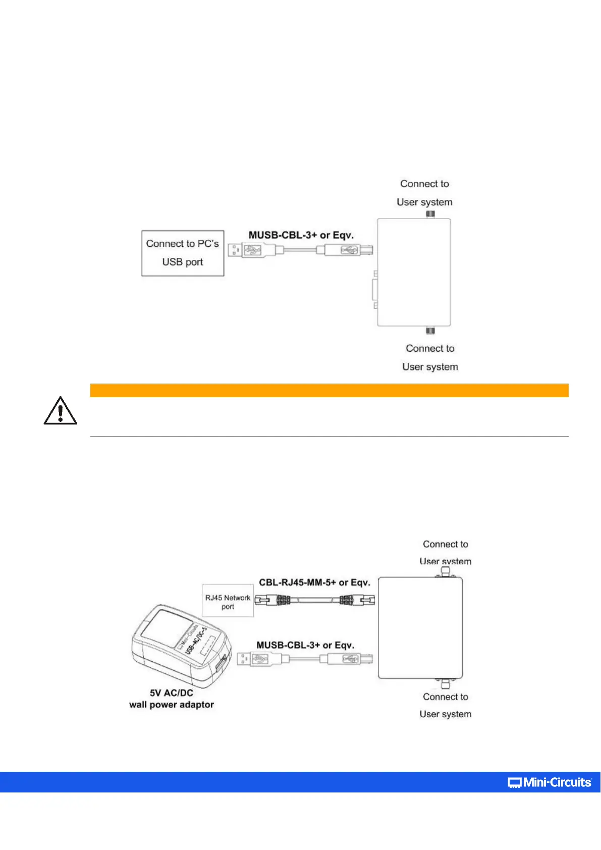
4.2. Ethernet Control
• Connect unit to power source via USB cable or the provided power adaptor.
• Connect a standard network cable between the unit’s RJ45 socket and the network port.
• Ensure the network indicators on the unit’s RJ45 socket light up after a few seconds.
• Connect the unit’s input and output RF ports to your system.