AN-49-011 © 2023 Mini-Circuits
Rev. D | ECO-016581 | 25-Jan-2023 Page 14
4.3.1. Setup Instructions
Digital & DC connections for daisy-chain control can be done in any order so long as addresses are refreshed once all units and
power supplies are connected.
1. Arrange the required modules on the work surface in the order they are to be addressed.
2. Use the serial control cables (CBL-1.5FT-MMD+, CBL-5FT-MMD+, or equivalent) to connect the units together in the daisy-
chain, from Serial CTRL Out of the first unit, to Serial CTRL In of the second, and so forth.
3. Note the DC current draw of each module in the daisy-chain from the published datasheets.
4. Starting from the first module in the daisy-chain, sum the DC current draw of each module to confirm whether the total
exceeds the maximum pass-through current (500 mA), or the maximum available from the USB supply (if lower).
5. If required, connect an additional 5V DC power supply to the USB port of one of the daisy-chained modules, to keep the DC
consumption of the previous group beneath the specified limit.
6. Repeat the check from this module forward and add additional power supplies as necessary.
7. Finally, connect the USB cable from the first module to the control PC and the complete chain will power up and
automatically assign address (from 00 to nn).
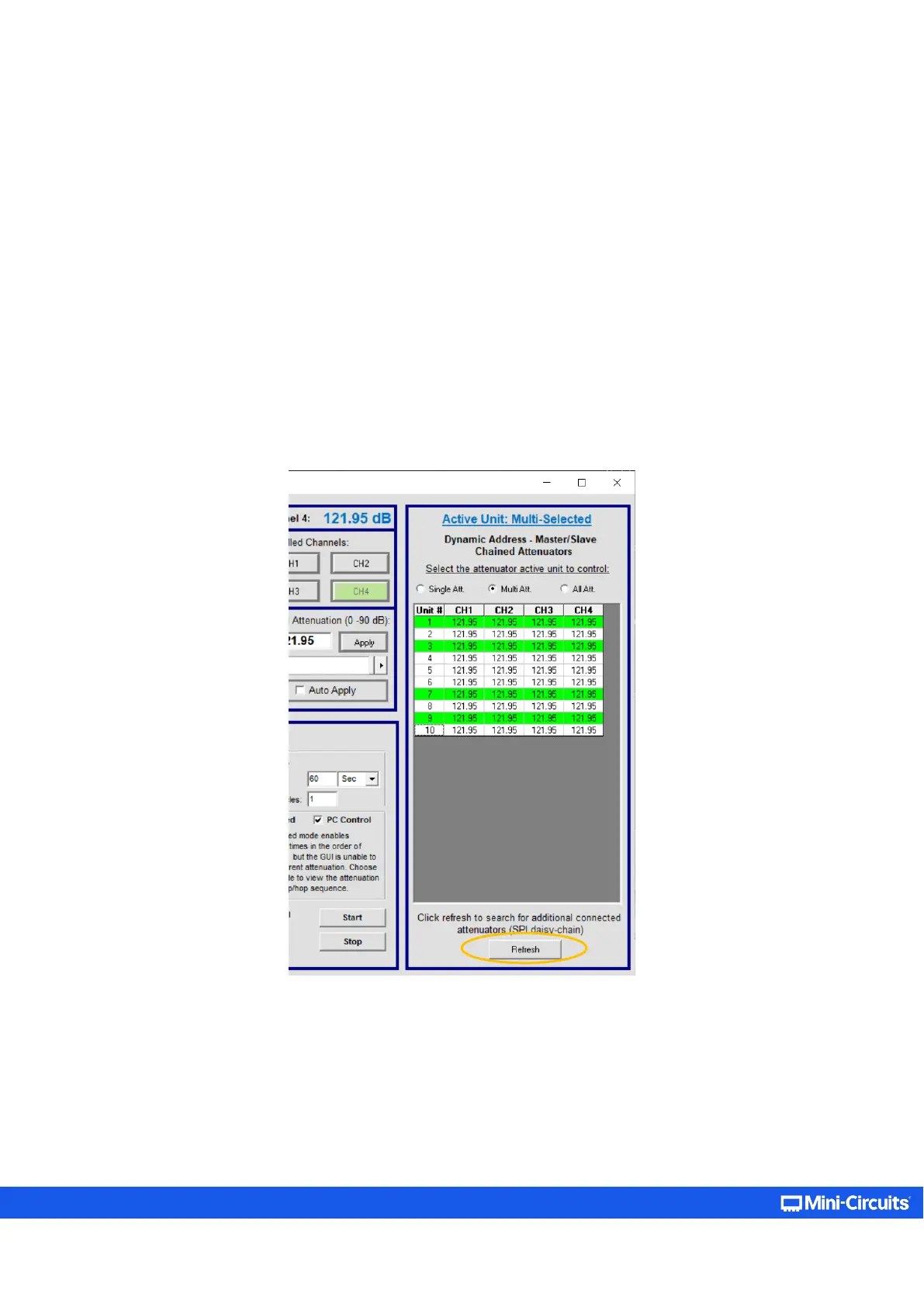
8. To add additional units to the daisy chain, just repeat step 6 from the last unit connected to a power supply, then connect
the additional units with serial control cables and click on the address Refresh button in the GUI (located below the
connected units list).
Figure 4.3.1: List of connected units on the daisy-chain section of the GUI (appearing for supporting models only)