AN-49-011 © 2023 Mini-Circuits
Rev. D | ECO-016581 | 25-Jan-2023 Page 29
5.4.5. Attenuator Switching Time
Attenuator models are specified with typical switching times of 650 ns, but even faster transitions can be observed in practice.
Switching time in this instance is defined as the time during which the attenuator is transitioning from one attenuation level to
the next. This short switching time means the RF signal path has an undefined attenuation state for as short a time as possible
during changes in attenuation levels. Switching time is distinct from minimum dwell time during a sweep or hop sequence which
is generally dictated by communication and control delays rather than RF switching characteristics.
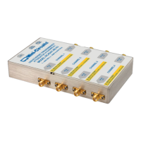
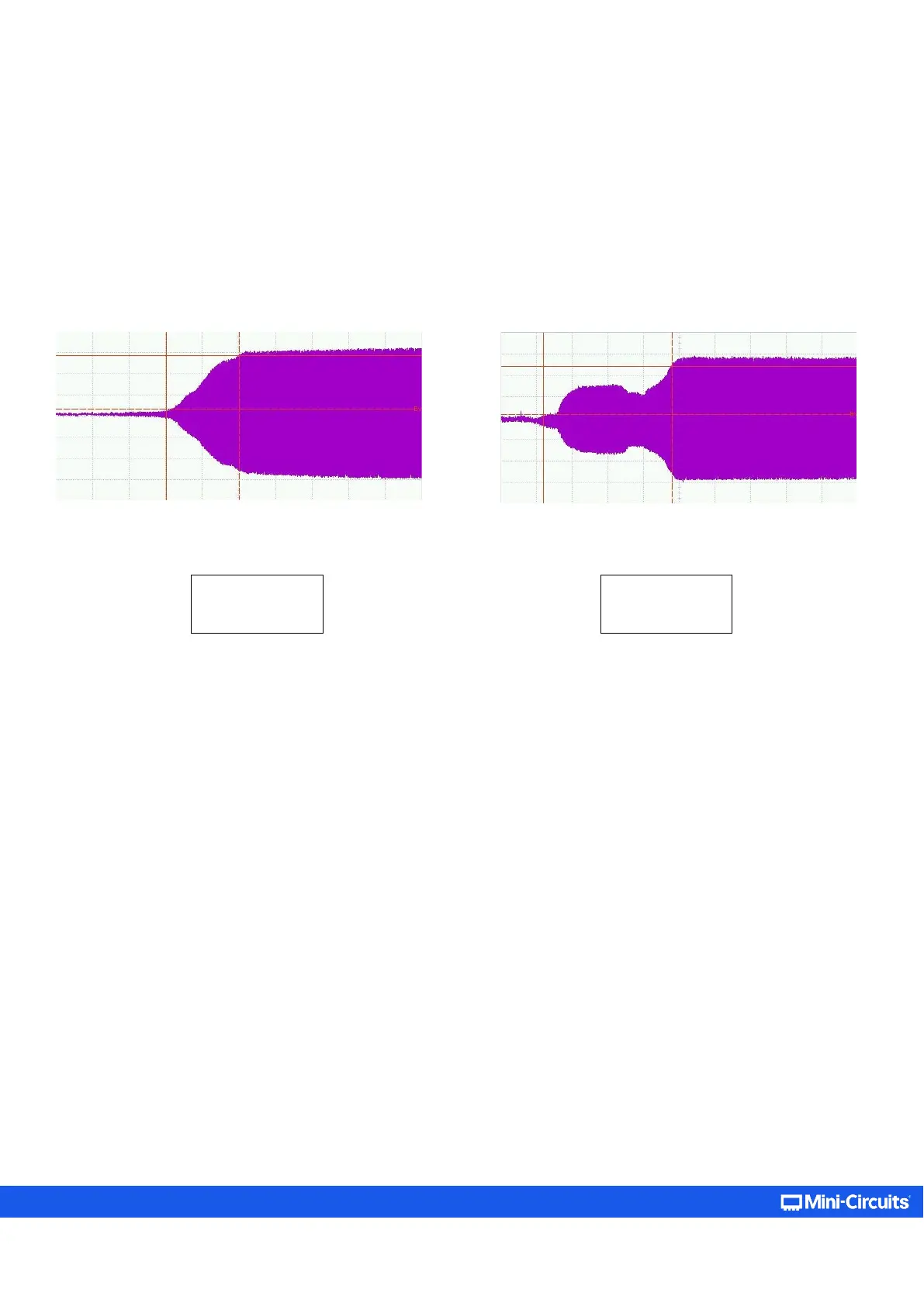
Some typical switching time measurements applicable to the programmable attenuator series are presented below:
Figure 5.4.5b: Typ. Switching time from 45 to 15 dB (RCDAT-
4000
-120); 362 ns switching time achieved
Figure 5.4.5a: Typ. Switching time from 120 to 0 dB (RCDAT-
4000
-120); 200 ns switching time achieved