RXD 2
TXD 3
GND 5
RTS 7
CTS 8
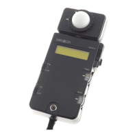
Data can be transferred between the instrument and a PC by connecting the instrument’s RS-232C
terminal to a PC.
When using the instrument continuously for long periods of time or when performing data transfer
using the RS-232C terminal, we recommend using the AC adapter (AC-A17) when connected to a PC
because of the higher power consumption involved.
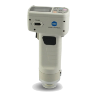
<Connecting the PC>
By connecting the instrument to a PC/AT compatible PC using the optional RS-232C cable CR-A102,
the data stored in the instrument memory can be sent to a PC.
Use the optional CR-400 utility software CR-S4w or the Color data software ChromaMagic CR-S3w
when connecting the instrument to a PC.
The followings can be used in remote mode:
1. Outputting measurement and target color data to a PC
2. Deleting measurement data
See P.129 “Changing to Remote Mode” for details.
Notes on Use
• When connecting, make sure that the connectors are correctly oriented and fastened securely with
screws.
• Before connecting, make sure that the power to both the instrument and PC is turned OFF.
• Hold the connector when connecting or disconnecting. Do not bend, pull, or apply undue pressure
to the cord, as this may cause it to break.
• Do not touch the connector terminals with your hand. Doing so may cause them to get dirty or
subject them to excessive force.
• Make sure that the cable is long enough. Tensioning the cable may cause connection failure or wire
breakage.
• If optional RS-232C cable CR-A102 is not used, make sure the cable specifications match the pin
number/signal connection diagram for an RS-232C cable below. An inappropriate cable will pre-
vent data from being input and output properly and may cause malfunctions.
• Communication Parameters
• RS-232C connection cable pin number/signal connection diagram
Connecting to External Devices
Item Setting
Baud rate 19200bps
Charactor length
Parity
Stop bit 1bit
8bit
None
Instrument PC
(for D-sub 9 pins)
Signal Pin No.
Pin No. Signal
 Loading...