18 (2181)
REPAIR GUIDE
aa
aa
a
bb
bb
b
aa
aa
a
bb
bb
b
■■
■■
■
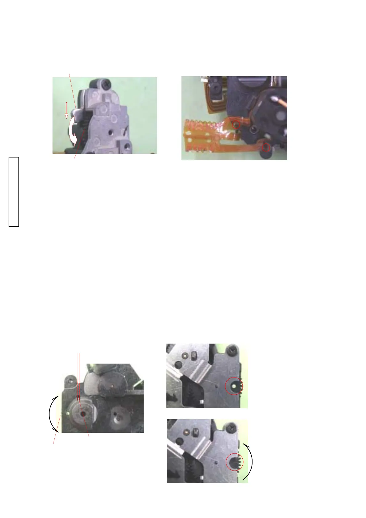
Fig. 1 AF CHARGE ASSY InstallationFig. 1 AF CHARGE ASSY Installation
Fig. 1 AF CHARGE ASSY InstallationFig. 1 AF CHARGE ASSY Installation
Fig. 1 AF CHARGE ASSY Installation
1. Rotate the designated cam-gear in arrow direction while keep pushing the lever against it1. Rotate the designated cam-gear in arrow direction while keep pushing the lever against it
1. Rotate the designated cam-gear in arrow direction while keep pushing the lever against it1. Rotate the designated cam-gear in arrow direction while keep pushing the lever against it
1. Rotate the designated cam-gear in arrow direction while keep pushing the lever against it
until the lever descends down to the lowest.until the lever descends down to the lowest.
until the lever descends down to the lowest.until the lever descends down to the lowest.
until the lever descends down to the lowest.
2. Arrenge the flexes.2. Arrenge the flexes.
2. Arrenge the flexes.2. Arrenge the flexes.
2. Arrenge the flexes.
LeverLever
LeverLever
Lever
Cam-gearCam-gear
Cam-gearCam-gear
Cam-gear
APERTURE BASEPLATE ASSY Setting
Firstly confirm APERTURE BASEPLATE ASSY is at the default position (Spare parts are supplied at the
default position) then set the charge position before installation.
Default Position Check/ Setting
1. Confirm on which side (a or b in Fig. 2) in the square opening (of APERTURE BASEPLATE
ASSY) the spring leg lies.
2. Turn the aperture reduction gear in the direction opposite to the spring location (a or b in Fig. 2)
until the spring leg moves over to the other side.
e.g. IF the spring lies at a in Fig. 2, turn the gear toward a in Fig. 2.
3. With the above condition, turn the aperture reduction gear slightly until its through hole aligns with the
through hole of the aperture baseplate-B (Fig. 3). This is the default position.
Charge Position Setting
1. Make sure that APERTURE BASEPLATE ASSY is set to the default position.
2. Charged position of APERTURE REDUCTION GEAR
a) View from the front of APERTURE BASEPLATE ASSY.
b) Turn APERTURE REDUCTION GEAR to counterclockwise direction 3 times and turn additional 120
degrees to the same direction and then "-" sign is appeared on the APERTURE REDUCTION GEAR.
APERTURE REDUCTION GEAR is set to charged position. (Fig. 4)
■■
■■
■
Fig. 2 BottomFig. 2 Bottom
Fig. 2 BottomFig. 2 Bottom
Fig. 2 Bottom
Spring legSpring leg
Spring legSpring leg
Spring leg
■■
■■
■
Fig. 3 TopFig. 3 Top
Fig. 3 TopFig. 3 Top
Fig. 3 Top
Aperture reduction gearAperture reduction gear
Aperture reduction gearAperture reduction gear
Aperture reduction gear
(Through hole)(Through hole)
(Through hole)(Through hole)
(Through hole)
Aperture reduction gearAperture reduction gear
Aperture reduction gearAperture reduction gear
Aperture reduction gear
Aperture reduction gearAperture reduction gear
Aperture reduction gearAperture reduction gear
Aperture reduction gear
((
((
(
――
――
―
: Mark): Mark)
: Mark): Mark)
: Mark)
■■
■■
■
Fig. 4 TopFig. 4 Top
Fig. 4 TopFig. 4 Top
Fig. 4 Top
(Default Position)(Default Position)
(Default Position)(Default Position)
(Default Position)
(Charge Position)(Charge Position)
(Charge Position)(Charge Position)
(Charge Position)

 Loading...