MIOX RIO Series Operators Manual
P/N: 102-00076-G Page 40
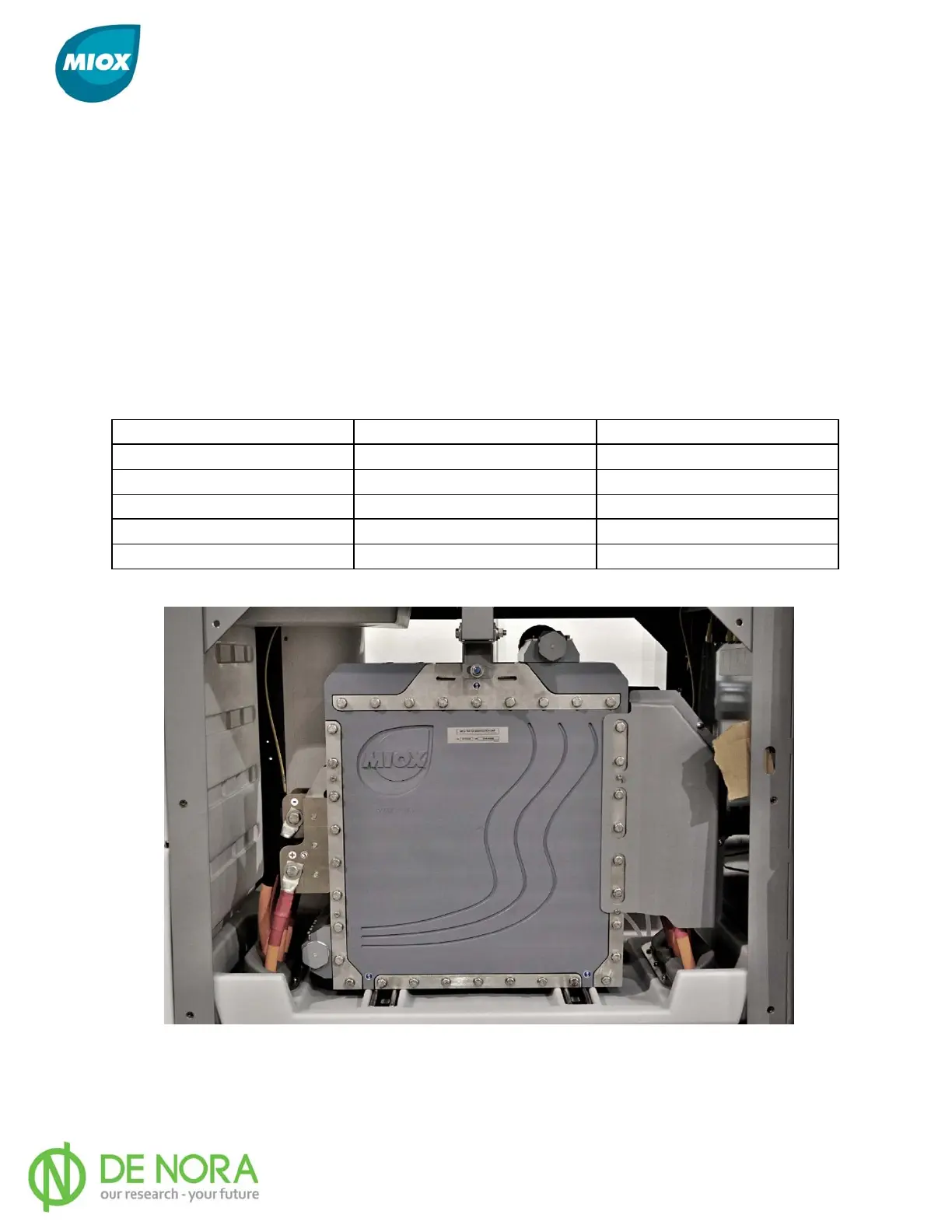
Electrical Connections
Connection of the cell electrical leads to the cell is accomplished by matching the red leads to
the anode or positive buss bars and the black leads to the cathode or negative buss bars.
Electrical connections are determined by number of cell modules in the cell assembly. Each
electrode/ buss bar must be connected to an electrical lead on both sides of the cell (Figure
24). The anode or positive buss bar is always the first electrode facing the front of
the unit. The cathode or negative buss bar is the next electrode behind the anode. This
alternating electrode configuration will continue depending on the number of cell modules.
Table 9 identifies the number of electrical connections (+/-) based on the number of
modules.
Table 9 Electrical Connections Per Cell Module
Cell Configuration # of Red (+) Leads # of Black (-) Leads
M1/H1 2 2
M2/H2 4 2
M3/H3 4 4
M4/H4 6 4
M5/H5 6 6
Figure 24 Cell Lead Connections