MIOX RIO Series Operators Manual
P/N: 102-00076-G Page 5
ListofFigures
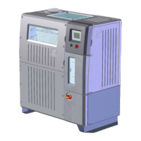
Figure 1 RIO Series On-Site Generator ............................................................................... 8
Figure 2 RIO Series OSG Space Requirements .................................................................... 9
Figure 3 RIO Series OSG Compartments .......................................................................... 15
Figure 4 Rear View of RIO OSG Showing Main Power Conduit .............................................. 16
Figure 5 Incoming Power ............................................................................................... 17
Figure 6 Switch Gear Cover ............................................................................................ 17
Figure 7 Power Routing to Switch Gear ............................................................................ 17
Figure 8 Rear Panel Connections ..................................................................................... 18
Figure 9 Tank Level Connector ........................................................................................ 19
Figure 10 Auxiliary Relay Connector ................................................................................ 20
Figure 11 Auxiliary 24V Power Connector ......................................................................... 21
Figure 12 Dilution Air Connector ..................................................................................... 22
Figure 13 H
2
/Hardness Connector .................................................................................... 23
Figure 14 Plumbing Enclosure ......................................................................................... 26
Figure 15 Feed Water, Brine, Y-strainer, and Oxidant Union Connections .............................. 27
Figure 16 Float Valve Assembly and Detail ........................................................................ 29
Figure 17 Internal View Float Valve Assembly and Detail .................................................... 30
Figure 18 Brine Pressure Boost System ............................................................................ 32
Figure 19 Oxidant Tank Vents ......................................................................................... 33
Figure 20 Oxidant Storage Tank with Safety Placards ......................................................... 34
Figure 21 Ventilation Requirements ................................................................................. 35
Figure 22 Level Switch Installation .................................................................................. 36
Figure 23 Pressure Transducer Assembly .......................................................................... 37
Figure 24 Cell Lead Connections...................................................................................... 40
Figure 25 Cell Lead and Buss Bar Connection .................................................................... 41
Figure 26 Cell Plumbing Connectons - 1 Module ................................................................ 42
Figure 27 Multiple Module Cell Inlet/Outlet Manifold ........................................................... 43
Figure 28 Cell Guard Pre-Assembly .................................................................................. 44
Figure 29 Location of Socket Head Shoulder Screws – Back ................................................ 45
Figure 30 Location of Socket Head Shoulder Screws - Front ................................................ 45
Figure 31 Display Screen, Run/Stop Switch, and Disconnect Switch ..................................... 48
Figure 32 Main Display Screen ........................................................................................ 49
Figure 33 Switch Gear Panel Components ......................................................................... 65
Figure 34 Interface Board .............................................................................................. 66
Figure 35 Rupture Disk Ruptured Diaphragm .................................................................... 69
Figure 36 Rupture Probe ................................................................................................ 69