TX3 System
TX3 Telephone Access System Installation and Operation Manual 35
any device on the RS-485 network (using USB, a modem, or the COM port), you
can also connect to and configure any other device on the RS-485 network using
the TX3 Configurator.
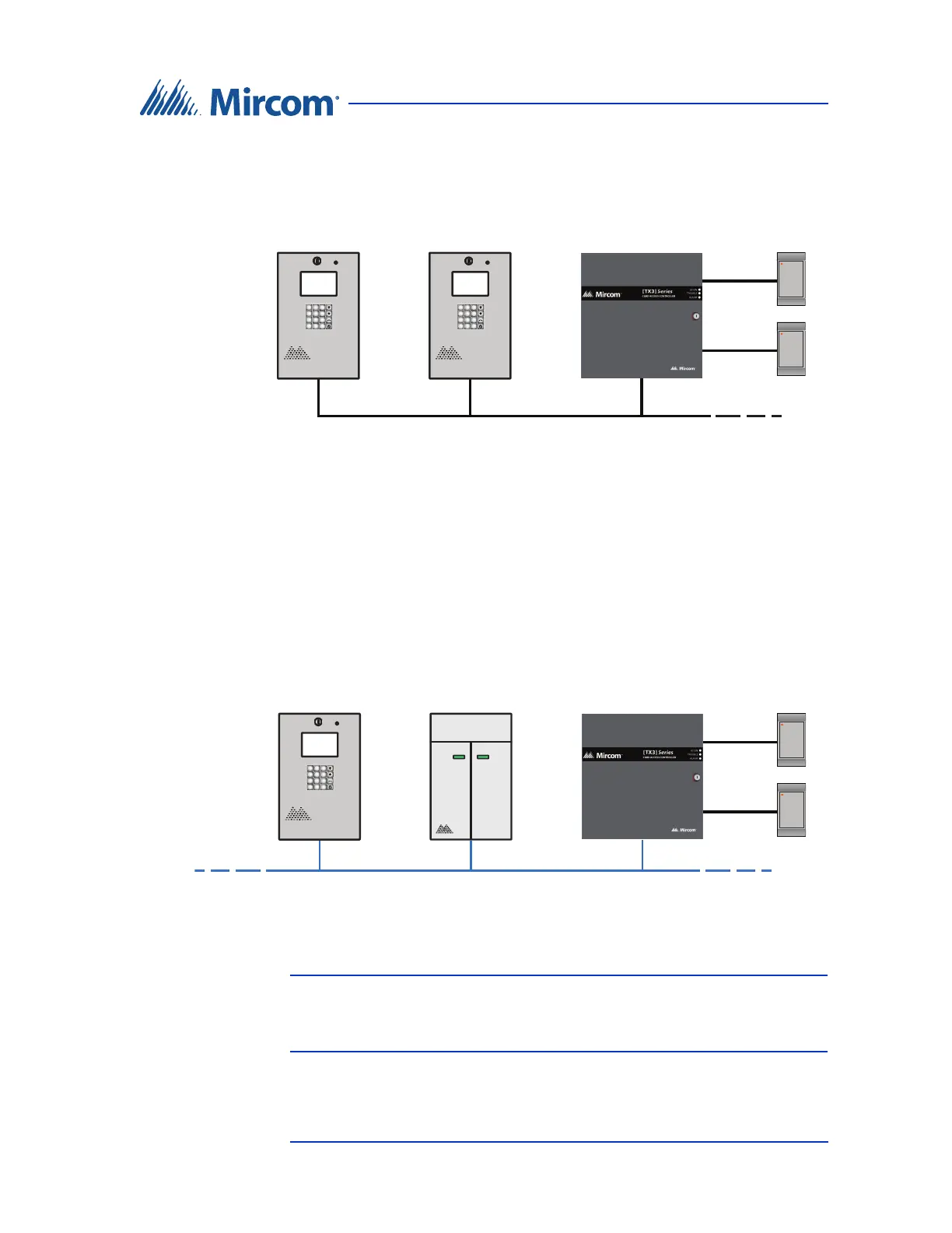
Figure 16. TX3 devices on an RS-485 network.
Figure 17 shows a configuration with TX3 devices connected to an Ethernet
TCP/IP network. This configuration removes the 63 device limitation that you
have on an RS-485 network. The devices connected to an Ethernet TCP/IP
network are called Master Nodes. If you connect to the TCP/IP network with the
TX3 Configurator, you can connect to and configure any of the Master Nodes on
the Ethernet TCP/IP network. If you connect directly to one of the Master Nodes
using USB, a modem, or a COM port, you will be able to configure that device
but not any other device.
Figure 17. TX3 devices on an Ethernet TCP/IP network.
Notes: In order for a panel to connect to an Ethernet TCP/IP network:
• it must have a TX3-IP IP Module installed, if it is not a
Touch Screen.
Lobby Control Unit
Card Reader B
Card Reader A
Card Access Controller
RS-485 Network
2
ABC
3
DEF
1
5
JKL
6
MNO
4
GHI
8
TUV
9
WXYZ
7
PQRS
0
*
#
Lobby Control Unit
2
ABC
3
DEF
1
5
JKL
6
MNO
4
GHI
8
TUV
9
WXYZ
7
PQRS
0
*
#
Card Reader B
Card Reader A
Card Access Controller
(Master Node)
Ethernet Network
Lobby Control Unit
(Master Node)
2
ABC
3
DEF
1
5
JKL
6
MNO
4
GHI
8
TUV
9
WXYZ
7
PQRS
0
*
#
Elevator Restriction Unit
(Master Node)