Lobby Control Unit Setup
TX3 Telephone Access System Installation and Operation Manual 51
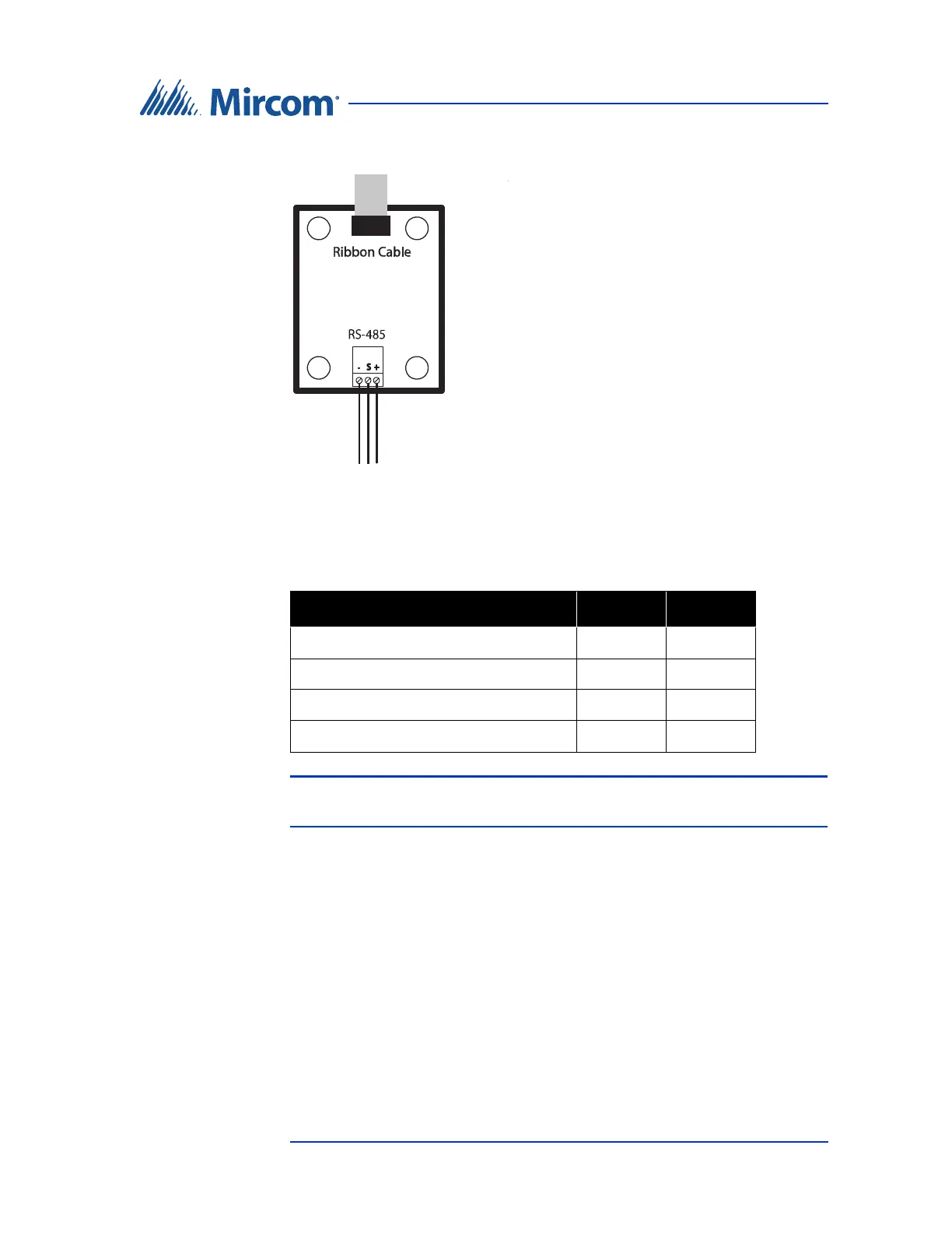
The module has an RS-485 connector as shown in figure 29.
Figure 29. RS-485 Add-on Module
For a description on how to install the RS-485 Add-on Module see the USB to
RS-485 Adapter Installation Instructions LT-6027.
Note: For the main application of the RS-485 Add-on Module, JW1 and
JW2 should both be shorted.
Table 1: RS-485 Add-on Jumper Settings
Mode JW1 JW2
No termination Open Open
AC termination 120R + 1nF Short Open
No termination Open Short
DC termination 120R (Factory Default) Short Short