46 TX3 Telephone Access System Installation and Operation Manual
Lobby Control Unit Setup
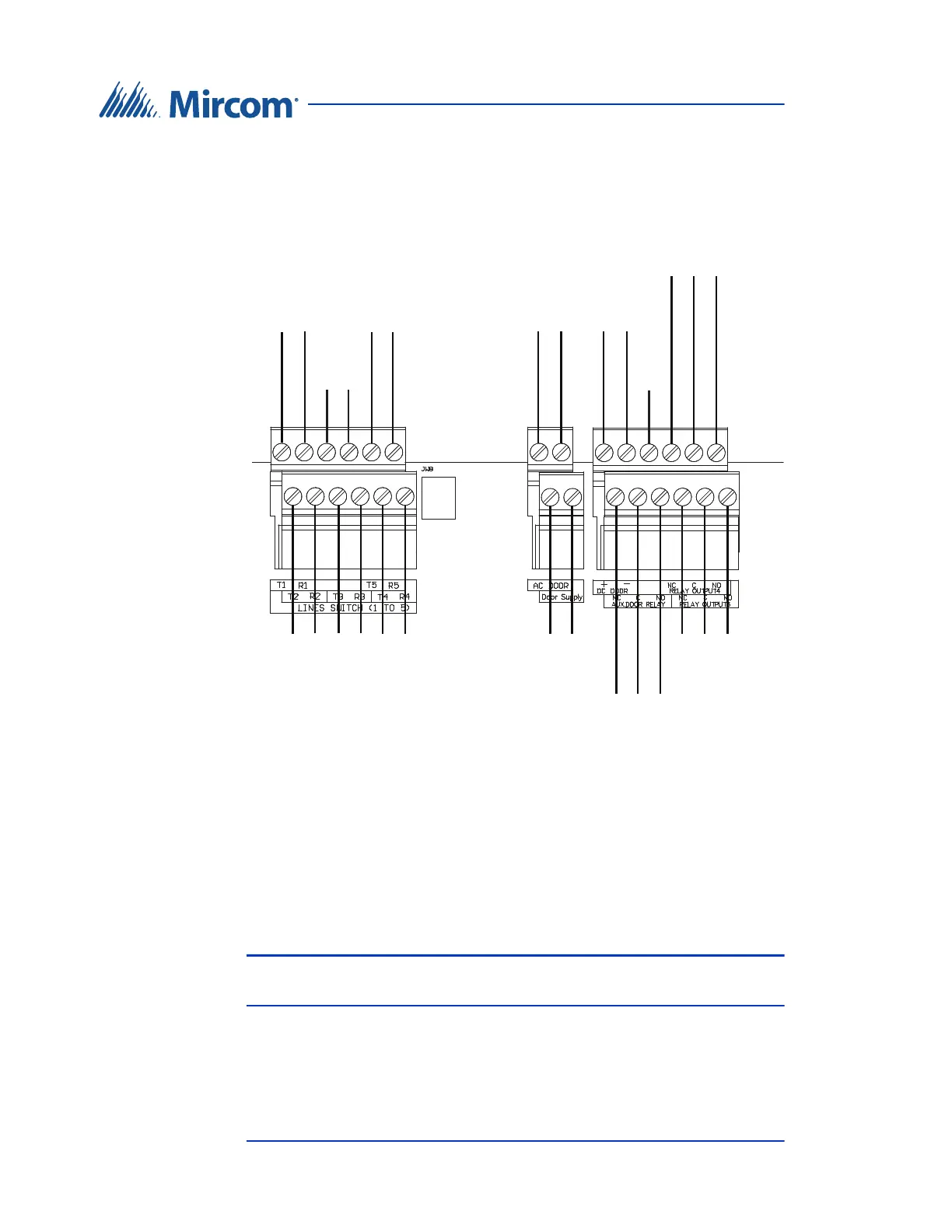
4.3 Controller Board Connectors - Top
Figure 25 shows the connectors at the top of the controller board.
Figure 25. Controller Board Connectors - Top
4.3.1 Telephone Lines 1 to 5
The telephone lines are situated at the top left of the main controller board.
Both NSL and ADC lines can be connected. Each T/R line is polarity insensitive
and can be reversed.
Note: Non-configurable PBX systems are not supported. For more
information, contact technical support at Mircom.
Line 1
T R
Line 2
T R
Line 3
T R
Line 5
T R
Line 4
T R
AC
Door Strike
AC or DC
Input Door
Strike Supply
DC Output 1
Door Strike
Output 4
Unused
JW8
NC C NO
NC C NO
General Relay
Output 3
Unused
NC C NO
Aux. Door
Output 2