Lobby Control Unit Setup
TX3 Telephone Access System Installation and Operation Manual 41
JW8. JW8 defines the operating state of the door strike relay as normally open or
normally closed. A jumper wire connects to either the normally open (position 2
- top) or normally closed pin (position 1 - bottom). The default setting is normally
open (position 2 - top).
JW9 and JW10. If there are problems with RS-485 communication, close both
JW9 and JW10 on either the first or last controller connected by RS-485. By
default these jumpers are open.
JW11: Leave open. This is the default setting.
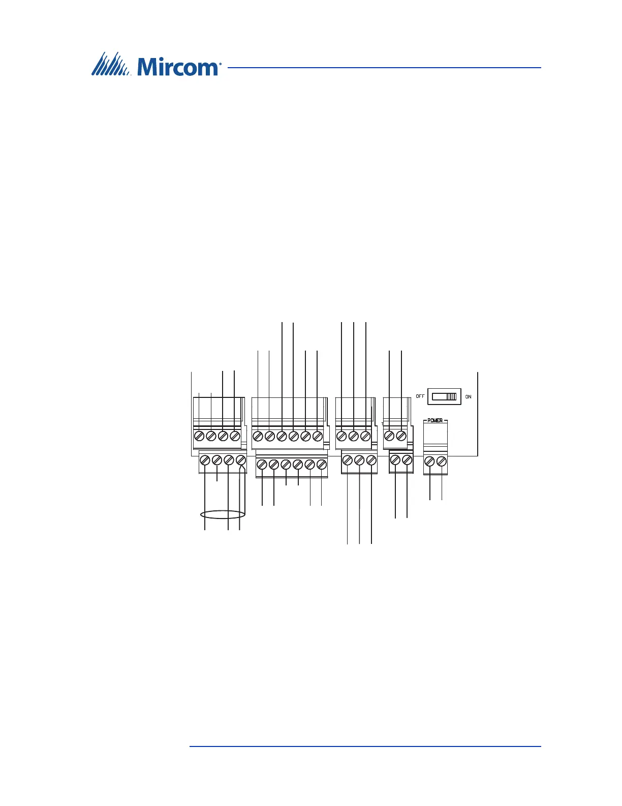
4.2 Controller Board Connectors - Bottom
Figure 21 shows the connectors at the bottom of the Lobby Control Unit main
controller board.
Figure 21. Controller Board Connectors - Bottom
4.2.1 Microphone Connection
The microphone connection is situated at the bottom left of the main controller
board. It connects to the front display and is factory set.
LED/LAMP
Supply
Input 1
Input 3
Input 5
Camera Supply
Power Supply for TX
3
(use 18 AWG)
RS-485 OUT
+
+ −
RS-485 IN
s
+−
+−
+−
Speaker
Connection
−
White
Microphone
Connection
Red Black
+−
+−
Input 2 Input 4
Unused
Unused
Unused
Sheild
+−
+−
s+−