EasyManua.ls Logo

Mitsubishi Electric SD Series User Manual

Mitsubishi Electric SD Series
160 pages
To Next Page IconTo Next Page
Page #1 background imageLoading...
Page #1 background image
MITSUBISHI ELECTRI
C
INDUSTRIAL AUTOMATION
MITSUBISHI ELECTRI
C
MELFA
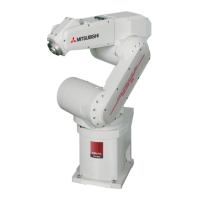
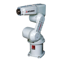
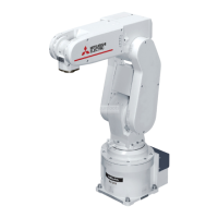
Industrial robots
Installation description
RV-SD/RH-SDH
RV-SQ/RH-SQH
Art. No.: 231407
06 01 2010
Version A

Table of Contents

Questions and Answers:

Mitsubishi Electric SD Series Specifications

General IconGeneral
CategoryRobotics
SeriesSD Series
Number of axes6
PayloadUp to 20 kg
ApplicationsAssembly, Material Handling
IP RatingIP67
MountingFloor, Ceiling, Wall

Summary

About this Manual

Manual Purpose and Contact Information

Explains the manual's scope, purpose, and how to get support.

Safety Instructions

Target Group and Usage Instructions

Defines authorized users and adherence to operational guidelines.

Safety-Relevant Regulations

Lists applicable German VDE and other safety regulations.

Hazard Instruction Commentary

Explains the meaning of DANGER and ATTENTION warning symbols.

General Hazard and Safety Measures

Provides general regulations for handling and operating the robot system safely.

Symbols Used in the Manual

Introduction

Model Name Conventions

Details the structure and meaning of robot model designations.

System Overview

Scope of Delivery

Lists the components included in the robot system package.

System Configuration

Describes the basic setup and components of SD and SQ robot systems.

Robot Arm Components

Identifies and explains the different axes and parts of the robot arm.

Control Units

Control Panel Overview

Details the front view of control panels for CRD and CRQ units.

CR2D Control Unit Components

Lists and describes the rear components of the CR2D control unit.

CR3D Control Unit Components

Lists and describes the components of the CR3D control unit.

CR2Q Control Unit Components

Lists and describes the components of the DU2 drive unit for CR2Q.

CR3Q Control Unit Components

Lists and describes the components of the DU3 drive unit for CR3Q.

Robot CPU (SQ Series)

Explains the external CPU for SQ series control units and its components.

Teaching Box

R28TB Teaching Box Controls

Details the controls and functions of the R28TB Teaching Box.

R32TB Teaching Box Controls

Explains the controls and functions of the R32TB Teaching Box.

R46TB and R56TB Teaching Boxes

Describes the controls and functions of the R46TB and R56TB Teaching Boxes.

Installation

Unpacking the Robot System

Step-by-step instructions for safely unpacking articulated and SCARA robot arms.

Transport Robot Arm

Guidelines for safely transporting robot arms, including holding points and precautions.

Set Up the Robot Arm

Procedures for properly setting and fixing articulated and SCARA robot arms.

Handling the Control Unit

Instructions for transporting and setting up control and drive units.

Installation of Robot CPU Q172DRCPU

Notes and procedures for installing the robot CPU module onto a rack.

Grounding the Robot System

Explains general instructions and methods for grounding the robot system.

Connection

Connection of Connection Cable

Shows how to connect the robot arm to the control unit using cables.

Robot CPU to Drive Unit Connection

Details the connection of the robot CPU to drive units DU2 and DU3.

Mains Connection and Grounding

Step-by-step guide for connecting the mains power and grounding the units.

EMERGENCY-STOP Connection

Explains how to connect emergency-stop pushbuttons and safety circuits.

Teaching Box Connection

Instructions for connecting the Teaching Box to the control unit or drive unit.

Startup

Calibrate the Robot System

Guides through switching on power and preparing for calibration.

Set Home Position (Zero Point)

Procedures for setting and saving the robot's home position using product insert data.

Operation of Teaching Box R32TB

Menu Tree

Illustrates the hierarchical structure and navigation of the R32TB Teaching Box menus.

Enter Character

Explains how to input alphanumeric characters using the Teaching Box interface.

Select Menu Item

Describes methods for navigating and selecting menu options on the Teaching Box.

Move Robot in JOG Mode

Details how to move the robot arm using different JOG modes for precise positioning.

Troubleshooting and Maintenance Instructions

Faults in Automatic Mode

Addresses issues that may occur during automatic robot operation and required actions.

Error Diagnosis

Explains how to interpret error codes displayed on the control unit or Teaching Box.

Replace Fuses

Provides guidance on identifying and replacing defective fuses in the system.

Maintenance Instructions

Outlines safety directives and general procedures for performing maintenance work.

Annex

Dimensions

Provides physical dimensions of robot arms.

Working Areas of the Robot

Illustrates the range of motion for various robot models.

Dimensions of Control Units, Drive Units, and CPU

Presents physical dimensions for system control components.

Related product manuals