4G1 ENGINE (E-W) -
Alternator and Ignition System
11A-3-1b
PWEE9520
E
Nov. 1995Mitsubishi Motors Corporation
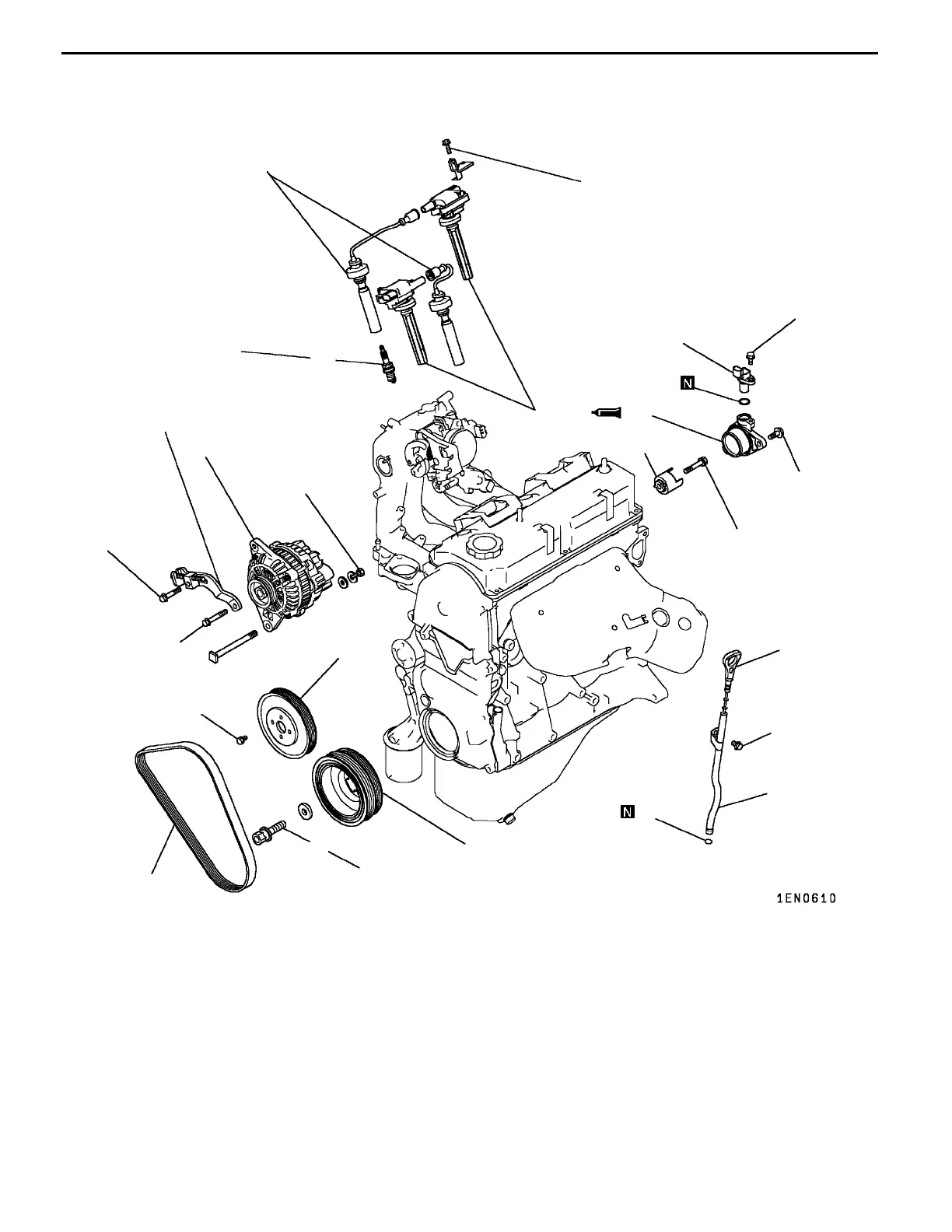
REMOVAL AND INSTALLATION <SOHC 16-VALVE-REAR WHEEL DRIVE>
22 Nm
6
7
44 Nm
23 Nm
4
125 Nm
8
9
3
2
23 Nm
1
11
10 Nm
10
13
13 Nm
9Nm
5
14
21 Nm
15
12
25 Nm
9Nm
Removal steps
1. Oil level gauge
2. Oil level gauge guide
3. O-ring
4. Drive belt*
5. Water pump pulley
6. Alternator brace
7. Alternator
A
A
""
B
A
8. Crankshaft bolt
9. Crankshaft pulley
10. Spark plug cable
11. Ignition coil
12. Spark plug
13. Cam position sensor
"
C
A
14. Cam position sensor support
15. Cam position sensing cylinder
NOTE
*: For details of adjustment, refer to the relevant model’s
chassis workshop manual.
PWEE9520-A
E
Dec. 1998Mitsubishi Motors Corporation Added
 Loading...


