3
Spindle orientation
J
control circuit
1
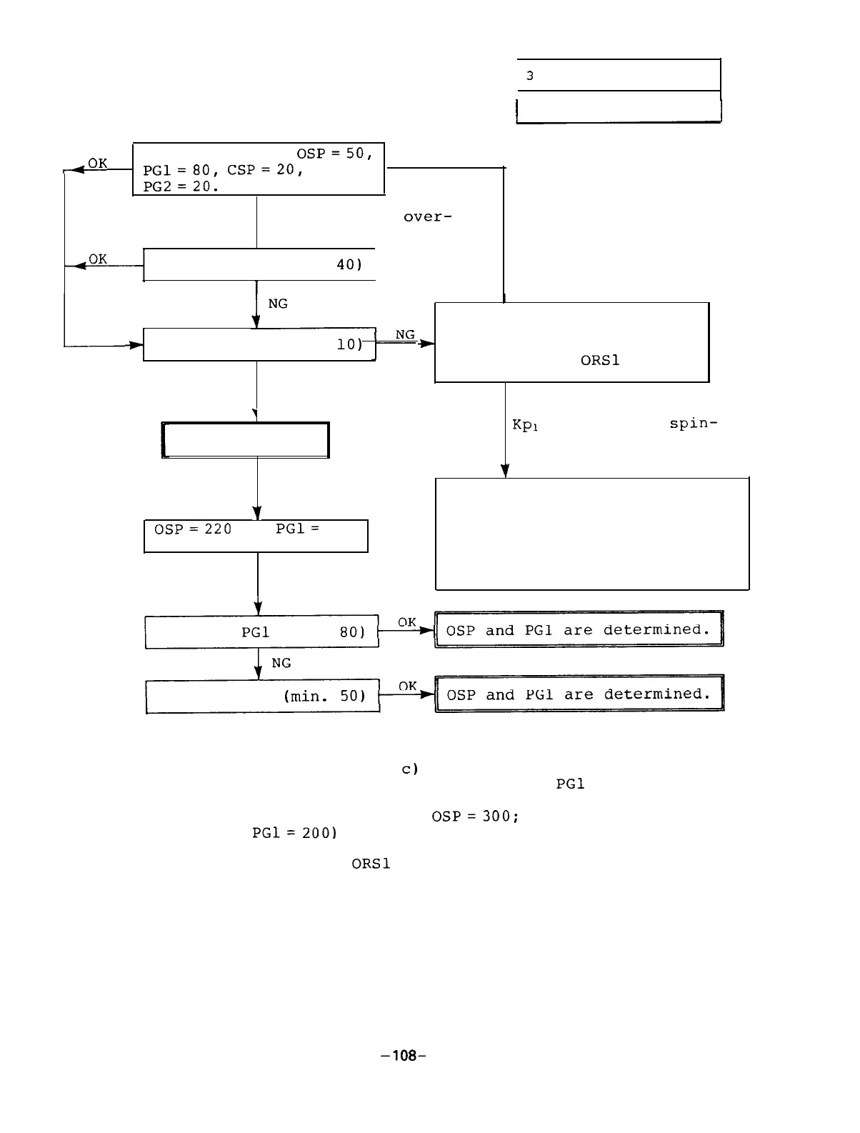
3.4 Adjustment
&OK
Set as follows:
OSP=50,
~~l=80,
cSP=~O,
and
4
PG2=20.
NG (The motor over-
, runs when it stops.)
The spindle does not
vibrate when it stops.
Increase PG2 (max.
40)
I
L
I
Increase bits 8 to B (Kp
magnification) and bit C
Decrease CSP (min.
10)
*
to F (Ki magnification) of
the parameter ORSl in the
same ratio.
OK
j
CSP and PG2 are
determined.
Without increasing
Kpl
and Ki, the
spin-
dle vibrates when it
stops.
v
Next step
7
1. Check that the magnesensor,
‘I
magnet,
and amplifier are
OSP=220
and
PGl=
133
not defective.
are determined.
2. Check that the SF-OR or
SF-TL card is defective.
3. Check that the mechanical
NG
system backlash is larqe.
Decrease
PGl
(min.
80)
Decrease OSP
(Note) 1.
2.
When the orientation time is long because the time
period (point b to
c)
on which the spindle rotates
at a creep speed,
increase OSP and
PGl
in the man-
ner that the spindle doesn't overrun when it stops.
(The maximum value of
OSP=300;
the maximum value
of
PGl=
200)
The parameter ORSl bits 0 to 3 (WT selection) are
the compensation gain for delay/advance of bit 4
(control method in servo lock situation).
Increase WT and the temporary servo rigidity in-
creases and the torque against the position devia-
tion decreases.
-108-

 Loading...