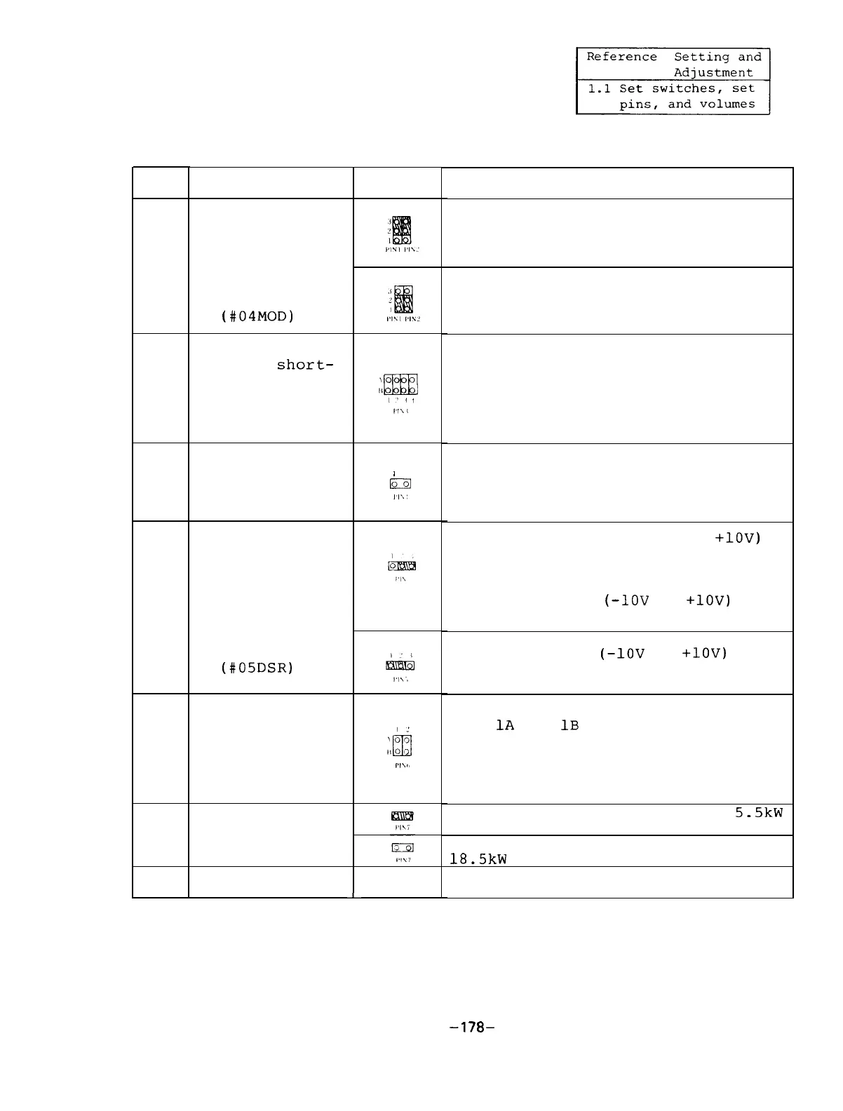
(4) Setting pins
No.
PIN1
PIN2
PIN3
PIN4
PIN5
PIN6
PIN7
PIN8
Name
Bus interface
setting
* The parameter
should be set
at the same
time.
(#04MOD)
Up/down short-
circuit protec-
tion time
setting
Converter check
test pin
Analog speed
reference
selection
* The parameter
should be set
at the same
time.
(#05DSR)
Control circuit
check test pin
Current loop
gain selection
L
Setting
/
lo
,‘I\’
Description
When the equipment is not linked to
the M300 series machine through the
bus.
When the equipment is linked to the
M300 series through the bus.
Sets an up/down shortcircuit pro-
tection time of a transistor.
If the setting is changed, the
transistor may be damaged.
Make
sure that the setting conforms to
the order list.
Test pin for delivery test.
Do not insert the pin when operat-
ing the equipment.
When unipolarity type (0 to
+lOV)
input is used:
If an offset voltage near 0 V
should be considered, the following
bipolarity type
(-1OV
to
+lOV)
should be used.
Bipolarity type
(-1OV
to
+lOV)
input
is used:
Test pin for delivery test.
When
1A
and
1B
are shortcircuited,
the controller overheat alarm can
be canceled.
When 2A and 2B are
shortcircuited, the breaker trip
alarm can be canceled.
When the capacity of FR-SF is 5.5kW
to 15kW.
When the capacity of FR-SF is
18.5kW to
.
(Currently not used)
-178-

 Loading...