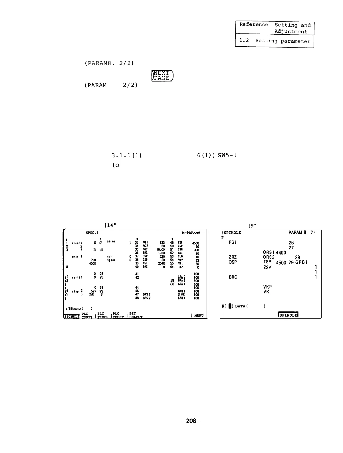
(3) Parameters to be controlled on spindle amplifier side
(PARAM8.
2/2)
By pressing the
key,
the spindle parameter screen
(PARAM
8.
2/2)
appears.
These parameters are sent from the NC when the spindle
amplifier is linked with the bus line.
(Note 1) Although the same parameters can be set from the
spindle amplifier,
when the bus line is linked,
those being set from the NC become valid.
(Note 2) When the SF-CA card dip switch (see Section
3.1.1(l)
and Appendix
6(l))
SW5-1
is turned on
(o
mark),
the parameters being set from the NC
are invalidated and those set from the spindle
amplifier is validated.
[14”
CRT
screen]
[SPINDLE
SPEC.1
n-PAuN49
I
I
,Imtll
o
,f
Iml”l
: :
4coO
790
I0
13
4 4
0
m
5
ImaIl
0
21
‘011
6 2
790 22
rp**r
7 3
40x
23
8 4
0
24
9
111l11
0
2
Kz
::
57 GRAI
56 cRA2
i:
:
3
0 27
43
4
3
*tap
1
52’:
t!!
::
zi
E::
i:
61
GRSl
: :
2640
0 30
31
:;
62 63 CR92
CM3
it
MS1
6601
6 4
0 32
40
MS2
0
64 CR84
:t
I
I
I-
19”
CRT screen]
JSPINDLE
SPEC.
1
PARAM0.
21
#
1
PGl 133 13
25GRAl
1
2
PG2
20
14
2
1
3
PGC
10.00
15
ORSl
44130
;!
3
1
.._.
4
ZRZ
1.00
16
0RS2
0023
26
4
1
5
OSP
220
17
TSP
4500
29GRBl
1
6
CSP
20
18
ZSP
50 30 2
1
7
PST 2048
19
CSN
300 31 3
1
8
BRC
0
20
SDT
1032 4
1
9 21
TLM
10 33
10
22
VKP
63 34
11
23
VKI
60 35
12
24
TYP
1 36
a(
1)
DATA(
1
BASE
AXIS
SERVO
-
MENU
(Note 3) After these parameters are set, the power of
the NC should be turned off.
After it is turned
on,
the parameters are validated.
-208-

 Loading...