(1)
Alarm
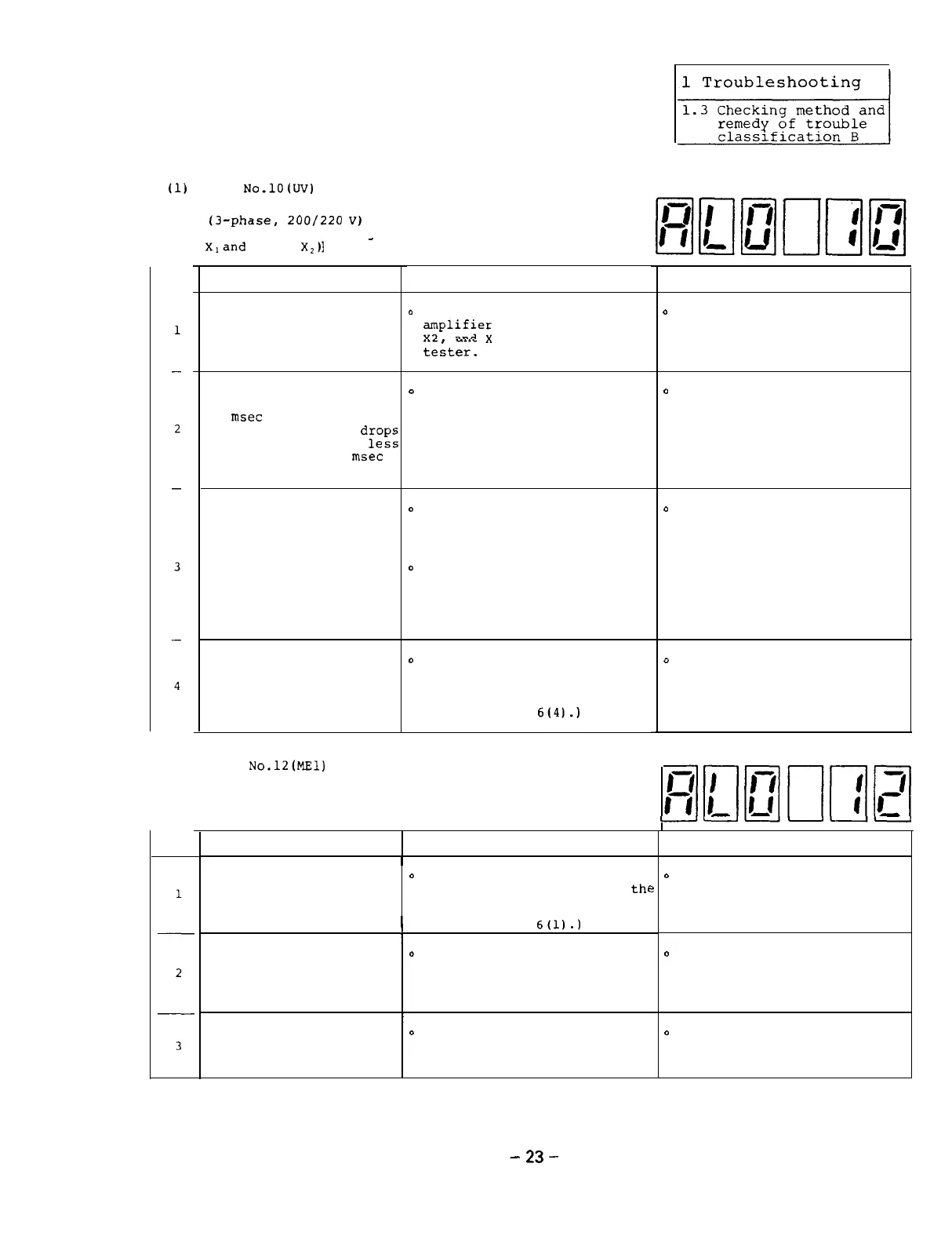
No.lO(UV)
Under Voltage
[The voltage drop of the input voltage
(3-phase,
ZOO/220
V)
to the amplifier
is detected. (Voltage between phase
_
Xland
phase
X,)1
Item
Cause Check
Remedy
0
Check the cause of which the
input voltage drops and take
proper countermeasures.
The AC input votlage of
the amplifier drops to
a voltage which is less
than 170 V.
0
Check the voltage at the
;plifier
input terminals Xl,
and X3 using a circuit
teiter.
0
Check the voltage waveforms
at the amplifier input termi-
nals Xl, X2, and X3 using an
oscilloscope.
0
Check the cause of the
instantaneous power failure
and take porper counter-
measures.
An instantaneous power
failure which lasts for
15
msec
or more occurs
(the input votlage
drop2
to a value which is
less
than 170 V for 15
msec
or more).
The power capacity is
insufficient.
0
Check the voltage waveforms
at the amplifier input termi-
nals Xl, X2, and X3 using an
oscilloscope.
0
Check that the input voltage
drops while the spindle
motor is in the acceleration/
deceleration state or while
an overload is applied.
o
Increase the power capacity.
0
Check that the voltage bet-
ween ACDOW and DO24 of the
block A in the SF-PW module
is + 5V.
(See Appendix
6(4).)
o
Replace the SF-PW module
with a new one.
The control power
(SF-PW module) is defec-
tive.
(2) Alarm
No.l20l!Zll
Memory Error 1
[The integrify of the contents Of
RO
M are compared with those of RAM
during initialization.]
-II-II-II
Item Cause
I
Check
Remedy
o
Install each ROM in the cor-
rect position.
EPROM is not installed
in the correct posi-
tion.
0
Visually check that ROM's 1,
2, and 3 are installed at
thl
correct positions on SF-CA
card.
e
1
(See Appendix
6(l).)
I
0
Visually check that pins of
ROM's 1, 2, and 3 are not
bent and they are correctly
inserted into the sockets.
There is an imperfect
connection between pins
of EPROM and the socket.
D
Straighten the pins being
bent and securely insert
them into the socket.
o
Replace the SF-CA card with
the new one.
(See Section 2.4.4).
The printed circuit
0
Replace the SF-CA card with
board SF-CA card is
a new one and check that the
defective. new one correctly works.
-
23
-

 Loading...