REAR AXLE – Troubleshooting <AYC>
27-11
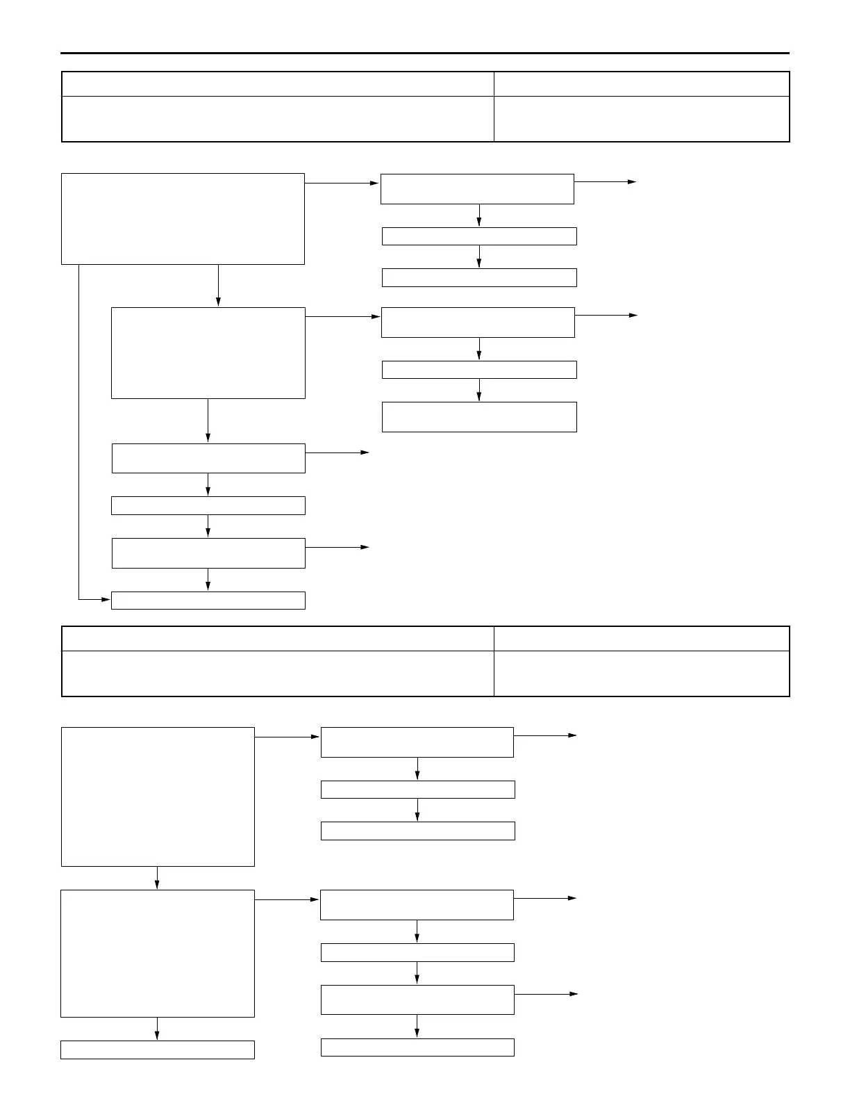
Code No. 31: Steer sensor (ST-1, ST-2, ST-N) system Probable cause
This code is output when any of the steer sensors ST-1, ST-2, and ST-N is open-circuited
or the steer sensor ground wire is open-circuited.
D Defective steer sensor
D Defective harness or connector
D Defective AYC-ECU
OK
Replace the steer sensor.
NG
Check the harness between steer sen-
sor and AYC-ECU.
NG
Repair
NG
Check and repair the harness between
speed sensor and AYC-ECU.
OK
Check the trouble symptom.
OK
Check the trouble symptom.
OK
Check the following connectors:
B-95, B-65, B-98
NG
Repair
NG: Voltage remains
at 4 V or more.
Measure at B-98 steer sensor connec-
tor.
D Disconnect the connector and
measure at the harness side.
D Continuity across 3 and body
ground
OK: Conducting
NG
Check the following connectors:
B-98, B-50
NG
Repair
NG
Replace AYC-ECU.
OK
Check the trouble symptom.
Measure at B-95 AYC-ECU connector.
D Connector connected.
D Ignition switch: ON
D Voltage across 4/5/17 and body ground.
OK: The voltage alternates between about
3 V and about 0.5 V when the steering
wheel is turned.
OK
Check the following connector:
B-95
NG
Repair
NG: Voltage alternates
between 4 V or
more and 0.5 V.
NG: Voltage
remains
at 0 V.
Code No. 32: Steer sensor (ST-N) system Probable cause
This code is output when the steering wheel is considered to be turned 40_ or more
as determined with ST-1 and ST-2 with ST-N ON (LOW voltage).
D Defective steer sensor
D Defective harness or connector
D Defective AYC-ECU
OK
Replace the steer sensor.
NG
Check the harness between steer sen-
sor and AYC-ECU.
NG
Repair
OK
Replace AYC-ECU.
NG
Replace AYC-ECU.
OK
Check the trouble symptom.
OK
Check the trouble symptom.
NG
Measure at B-95 AYC-ECU connector.
D Disconnect the connector and
measure at the harness side.
D Ignition switch: ON
D Turn steering wheel about 90_ in
either direction from the straight-
ahead position.
D Voltage across 17 and body
ground.
OK: No continuity
NG
Check the following connectors:
B-95, B-65, B-98
NG
Repair
Measure at B-95 AYC-ECU connector.
D Connector connected.
D Ignition switch: ON
D Turn steering wheel about 90_ in
either direction from the straight-
ahead position.
D Voltage across 17 and body
ground.
OK: The voltage increases from
about 0.5 V or less to about
3.5 V.
OK
Check the following connector:
B-95
NG
Repair

 Loading...