3-76
Options
3Controller
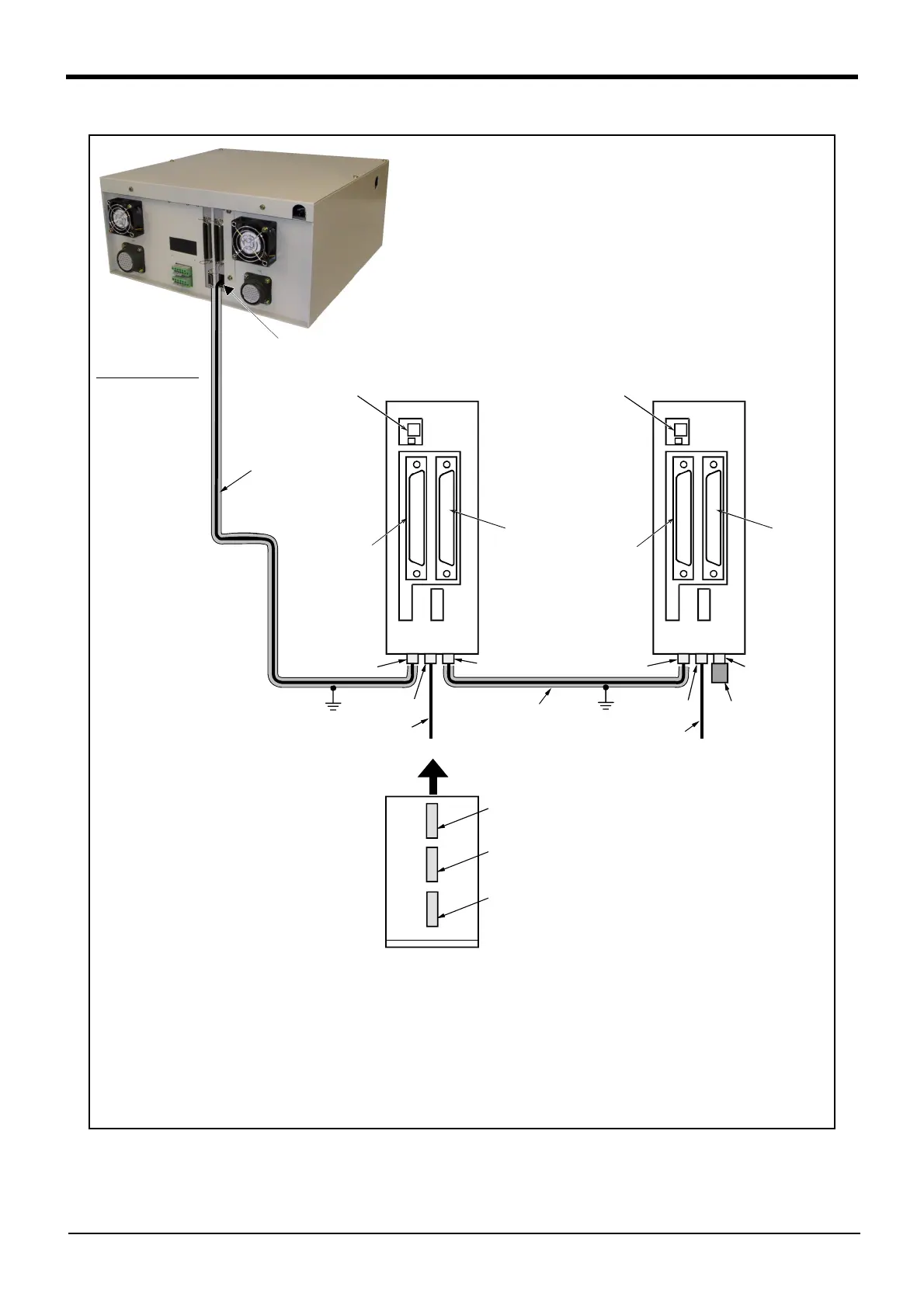
Fig.3-29 : Connection method of expansion parallel input/output unit (CR2B-574 controller)
<CN100>
<CN300>
<CN100>
<CN300>
DCIN
connector
DCcable-2
cable
RIO1 connector
RIO1 connector
NETcable-1
cable
DCcable-2
cable
RIO2 connector
RIO1 connector
DCIN connector
Front
FG
FG
Note)
Controller back side
Parallel I/O unit 1 . . . 6 Parallel I/O unit 7
Station No. setting
1 . . . 6
NETcable-1
cable
Note)
RIO2 connector
RIO2 connector
RIO1 connector
R-TM
terminator
Station No. setting
7
I/O unit the bottom
Connecta layout
DCIN
connector
Connect the NET cable-1 to the RIO1 connector on the back of the controller. Each unit is
connected to from a daisy chain.
Always install a terminator (R-TM) to the last unit.
Note) Use a shield cable for NET cable-1 as a measure against noise.
Always connect the shield to FG.
The unit could malfunction because of noise if the shield cable is not used.

 Loading...


