3-80
Options
3Controller
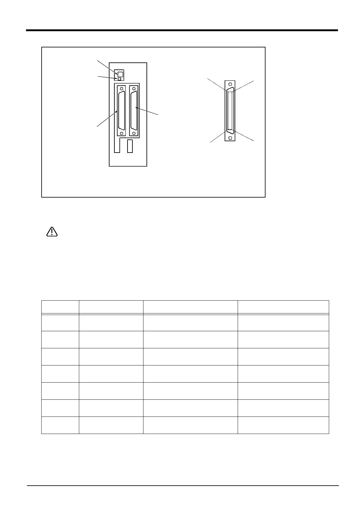
Fig.3-31 : Parallel input/output unit <2A-RZ361/2A-RZ371:Second expansion unit> connection and pin layout
[*1] For the 2nd expansion unit, set the channel No. to "2".
The channel No. of 8 to F is used for the maker test. If any value of 8 to F is set, it may
be dangerous since the robot unexpectedly moves. Don't set any value of 8 to F.
Table 3-21 lists the correspondence between the station numbers to be set and the I/O signal assignment.
Refer to this table when the third and subsequent units are used.
Table 3-21 : Station Number Settings and I/O Signal Assignment
Unit No. Station number setting CN100 CN300
1st unit 1 Input: 32 ~ 47
Output: 32 ~ 47
Input: 48 ~ 63
Output: 48 ~ 63
2nd unit 2 Input: 64 ~ 79
Output: 64 ~ 79
Input: 80 ~ 95
Output: 80 ~ 95
3rd unit 3 Input: 96 ~ 111
Output: 96 ~ 111
Input: 112 ~ 127
Output: 112 ~ 127
4th unit 4 Input: 128 ~ 143
Output: 128 ~ 143
Input: 144 ~ 159
Output: 144 ~ 159
5th unit 5 Input: 160 ~ 175
Output: 160 ~ 175
Input: 176 ~ 191
Output: 176 ~ 191
6th unit 6 Input: 192 ~ 207
Output: 192 ~ 207
Input: 208 ~ 223
Output: 208 ~ 223
7th unit 7 Input: 224 ~ 239
Output: 224 ~ 239
Input: 240 ~ 255
Output: 240 ~ 255
50
26
25
1
Channel No. setting
TXD
LED display
Input 64 to 79
Output 64 to 79
<CN100>
<CN300>
Input 80 to 95
Output 80 to 95
(Set channel No. to 2.)
*The 2A-RZ361/2A-RZ371 has 32 input and 32 output points unit
(Occupies one Channel)
[*1]
CAUTION

 Loading...


