12
TROUBLESHOOTING
12.2 Troubleshooting Flowchart
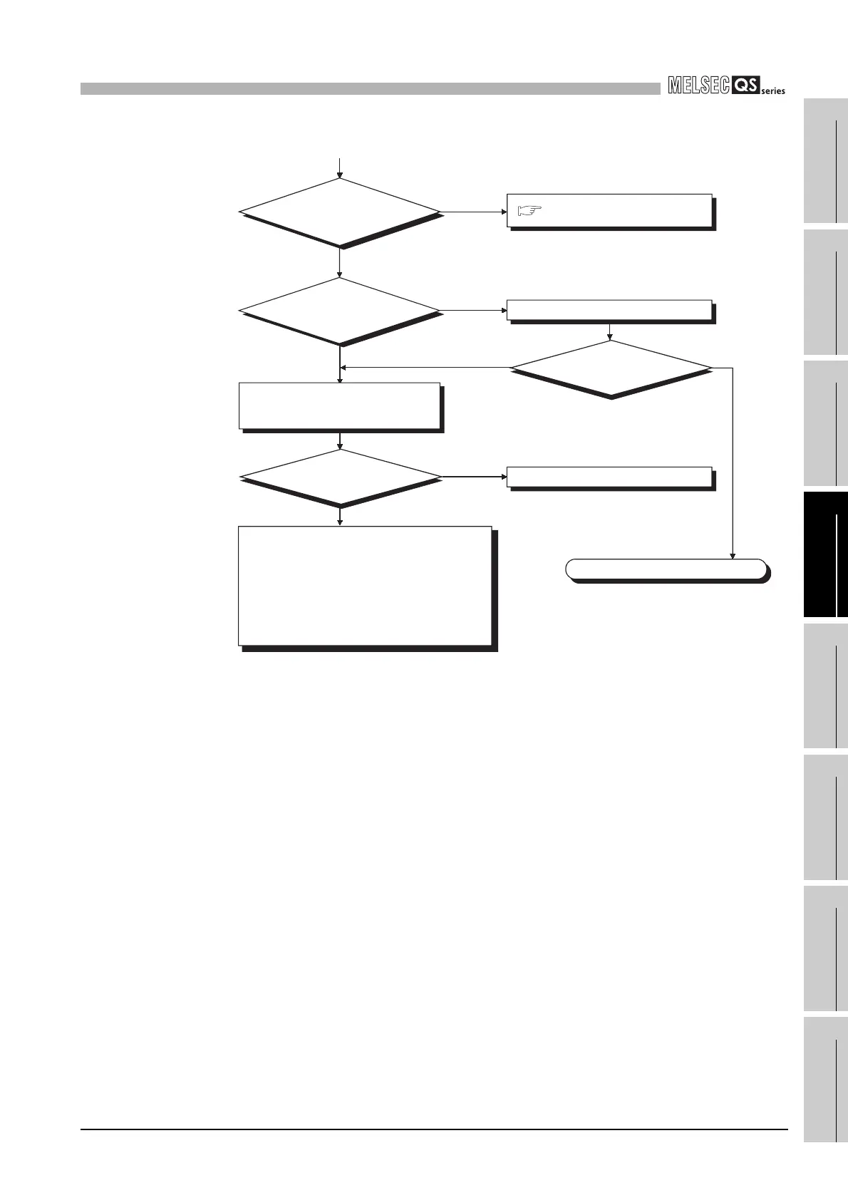
12.2.12 Flowchart for when the CPU cannot communicate with the GX Developer
12 - 19
9
EMC AND LOW
VOLTAGE
DIRECTIVES
10
LOADING AND
INSTALLATION
11
MAINTENANCE AND
INSPECTION
12
TROUBLESHOOTING APPENDICES INDEX
Hardware fault of power supply module.
Completed
NO
YES
RESET position
How is the "POWER" LED
of the power supply module?
Off
On
Is the CPU module
RESET/STOP/RUN switch in
the neutral position?
Other than RESET position
Cancel the RESET.
YES
NO
Can the CPU communicate
with the GX Developer?
Can the CPU communicate
with the GX Developer?
Flowchart for when
the "POWER" LED turns off.
(From previous page)
Replace the power supply module and
confirm that the "POWER" LED is on.
Hardware failure of the following modules
1) CPU module
2) Base unit
3) CC-Link Safety master module
4) Network module (if mounted)
Execute operation check sequentially from the
minimum system.
For the module that does not operate, please consult
your local Mitsubishi service center or representative,
explaining a detailed description of the problem.
Section 12.2.3

 Loading...

