9
EMC AND LOW
VOLTAGE
DIRECTIVES
10
LOADING AND
INSTALLATION
11
MAINTENANCE AND
INSPECTION
12
TROUBLESHOOTING APPENDICES INDEX
12
TROUBLESHOOTING
12.6 Special Reray List
12 - 69
(2) System information
(3) System clocks/counters
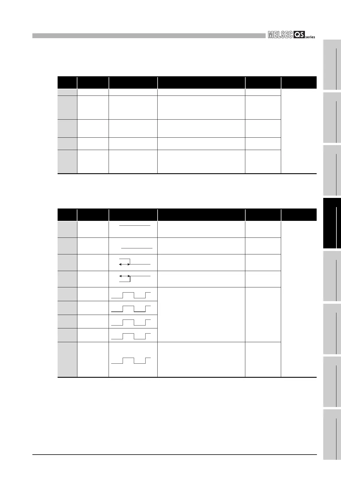
Table12.12 Special relay
Number Name Meaning Explanation
Set by
(When Set)
Corresponding
CPU
SM203 STOP contact STOP status • Turns ON when the CPU is in STOP status. S (Status change)
QS
SM210
Clock data set
request
OFF: Ignored
ON: Set request
• Writes clock data stored in SD210 to SD213
to the CPU module after the END instruction
of the scan where the relay changes OFF to
ON has been executed.
U
SM211 Clock data error
OFF: No error
ON: Error
• Turns ON when an error is detected in the
clock data (SD210 to SD213) and turns OFF
if no error is detected.
S (Request)
SM213
Clock data read
request
OFF : Ignored
ON : Read request
• Reads clock data to SD210 to SD213 in BCD
value when the relay is ON.
U
SM232
Number of
writes to ROM
OFF : Within the number
of writes
ON : Over the number of
writes
• Turns ON when the number of writes to ROM
exceeds 100,000.
S (Error)
Table12.13 Special relay
Number Name Meaning Explanation
Set by
(When Set)
Corresponding
CPU
SM400 Always ON • Normally is ON S (Every END)
QS
SM401 Always OFF • Normally is OFF S (Every END)
SM402
After RUN, ON
for 1 scan only
• After RUN, ON for 1 scan only. S (Every END)
SM403
After RUN, OFF
for 1 scan only
• After RUN, OFF for 1 scan only. S (Every END)
SM410
0.1 second
clock
• Repeatedly changes between ON and OFF
at each designated time interval.
• When PLC power supply is turned OFF or a
CPU module reset is performed, goes from
OFF to start.
S (Status change)
SM411
0.2 second
clock
SM412 1 second clock
SM413 2 second clock
SM414
2n second
clock
• This relay alternates between ON and OFF at
intervals of the time (unit: s) specified in
SD414.
• When PLC power supply is turned OFF or a
CPU module reset is performed, goes from
OFF to start.
S (Status change)
ON
OFF
ON
OFF
ON
OFF
1 scan
ON
OFF
1 scan
0.05s
0.05s
0.1s
0.1s
0.5s
0.5s
1s
1s
ns
ns

 Loading...

