EasyManuals Logo

Mitsubishi MELSEC User Manual

Mitsubishi MELSEC
200 pages
To Next Page IconTo Next Page
To Previous Page IconTo Previous Page
Page #183 background imageLoading...
Page #183 background image
12.7 Special Register List
12 - 83
12
TROUBLESHOOTING
9
EMC AND LOW
VOLTAGE
DIRECTIVES
10
LOADING AND
INSTALLATION
11
MAINTENANCE AND
INSPECTION
12
TROUBLESHOOTING APPENDICES INDEX
(5) Safety CPU
(6) Memory
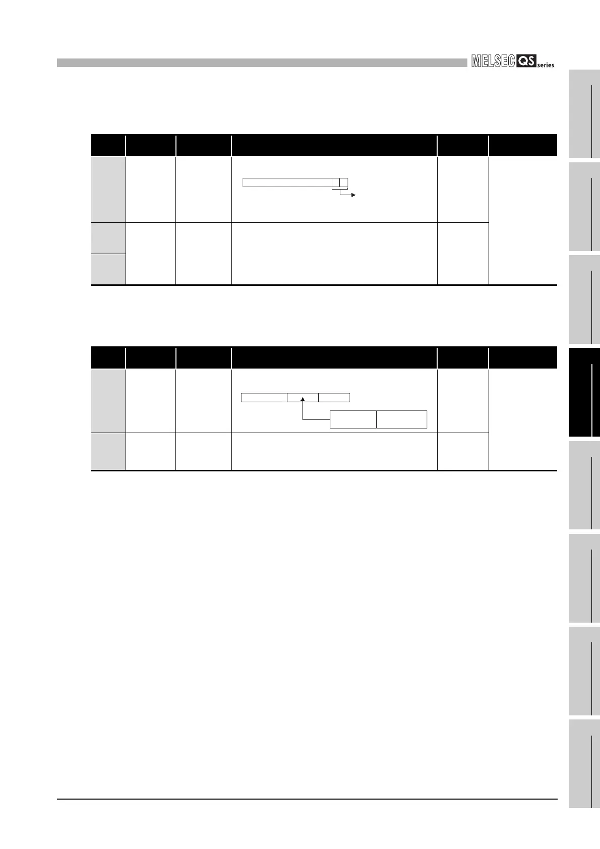
Table12.24 Special register
Number Name Meaning Explanation
Set by
(When set)
Corresponding
CPU
SD560
Safety CPU
operation
mode
Safety CPU
operation mode
Stores the safety CPU operation mode.
S (Status
change)
QS
SD561
TEST MODE
continuous
RUN time
TEST MODE
continuous
RUN time
(seconds)
Stores the TEST MODE continuous RUN time. (Measured in
seconds)
(RUN time in TEST MODE. Start measurement when STOP &
RUN (Time when operation is STOP is not included.)
Stores the measurment valve with the range of 1 to
2147483647.
S (Every END)
SD562
Table12.25 Special register
Number Name Meaning Explanation
Set by
(When set)
Corresponding
CPU
SD620 Memory type Memory type
Indicates the type of built-in memory.
S (Initial)
QS
SD623
Drive 4
(ROM)
capacity
Drive 4 capacity Drive 4 capacity is stored in 1 kbyte units. S (Initial)
b15 b2 b1b0
00 : SAFETY MODE
01 : TEST MODE
10 : SAFETY MODE
(Wait-for-restart)
to
Empty
b4 b3 b0
00
b8 b7b15
to toto
Drive 4
(Standrd ROM)
Fixed at
"3 (FLASH ROM)"

Table of Contents

Questions and Answers:

Question and Answer IconNeed help?

Do you have a question about the Mitsubishi MELSEC and is the answer not in the manual?

Mitsubishi MELSEC Specifications

General IconGeneral
CategoryProgrammable Logic Controller (PLC)
ManufacturerMitsubishi Electric
SeriesMELSEC
Programming LanguagesLadder Diagram (LD), Function Block Diagram (FBD), Structured Text (ST), Instruction List (IL), Sequential Function Chart (SFC)
Communication ProtocolsEthernet, CC-Link, RS-232, RS-485, USB, Profibus, Modbus
Model SeriesFX, Q, L, iQ-R, iQ-F
Input Voltage100-240V AC, 24V DC (varies by model)
Memory CapacityVaries widely depending on the CPU module and series. Ranges from kilobytes to megabytes.
I/O Points16 to 8192 points (varies by model)
Communication PortsEthernet, RS-232, RS-485, USB (varies by model)
Programming SoftwareGX Works2, GX Works3, GX Developer
Operating Temperature0°C to 55°C
Storage Temperature-25°C to 75°C
Humidity5% to 95% (non-condensing)
Vibration Resistance10 to 57Hz, 0.075mm amplitude; 57 to 150Hz, 9.8m/s² acceleration
Shock Resistance147m/s², 3 times in each direction (X, Y, Z)
Protection ClassIP20 (varies by model)
CPU Processing Speed0.02μs to 0.1μs per instruction (varies by model)

Related product manuals