2 - 2
2.1 System Configuration
2
SYSTEM CONFIGURATION
(2) System configuration overview
Precautions
• The extension base unit cannot be connected.
• The multiple CPU system cannot be configured.
• The modules which can be mounted on the I/O slot are the CC-Link Safety
master module, CC-Link IE controller network module, MELSECNET/H
module, Ethernet module, and blank cover only.
If a module other than the ones mentioned above is mounted, "MODULE
LAYOUT ERROR" (error code: 2125) is detected.
Note, however, that a "MODULE LAYOUT ERROR" is not detected for the
slot where "Empty" has been set in the I/O assignment setting of PLC
parameter.
• GOTs cannot be connected.
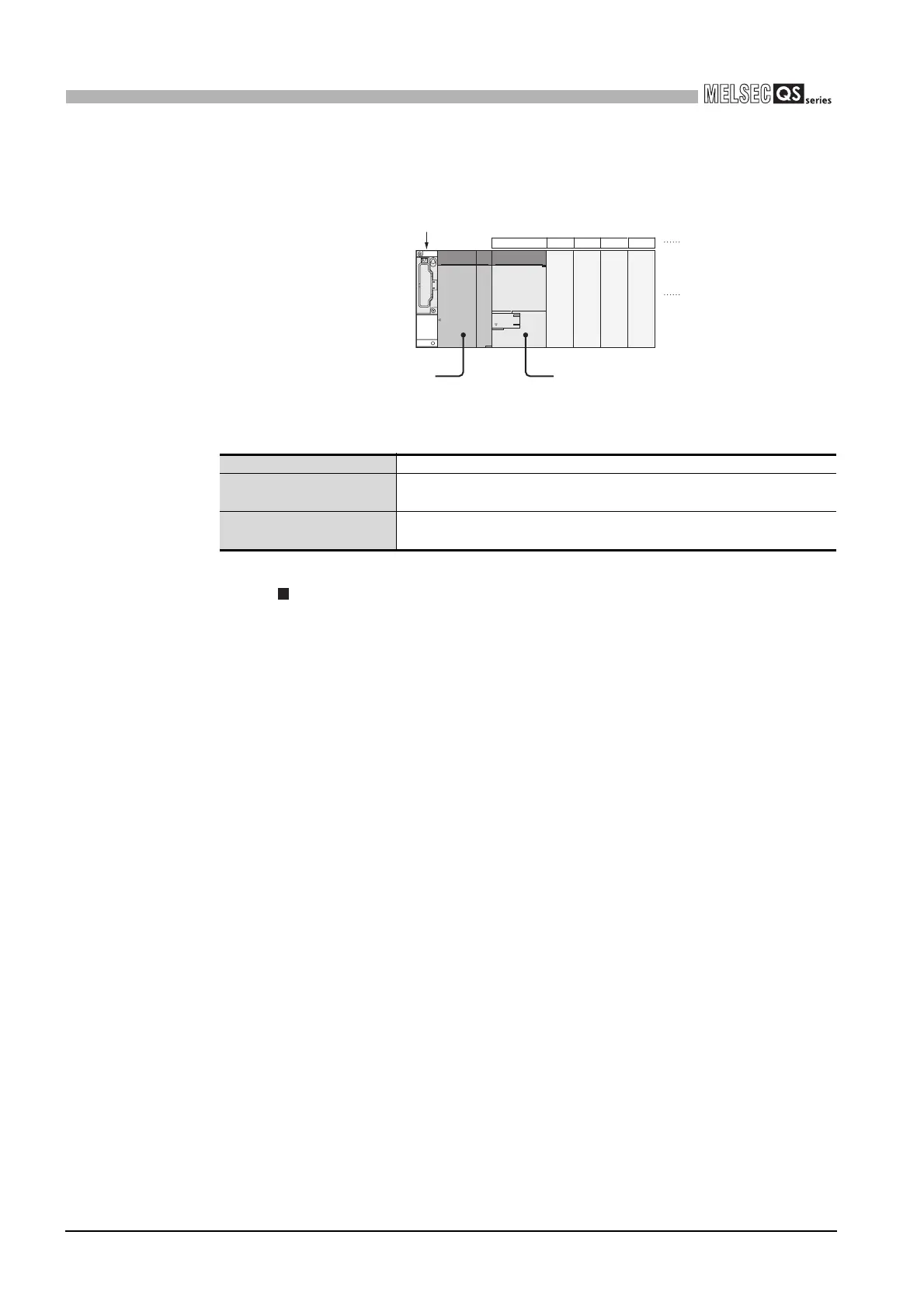
Figure 2.2 System configuration
Table2.1 Base unit and power supply module applicable to system configuration
Base unit model name QS034B
Maximum number of monted
modules
4 modules
Power supply module model
name
QS061P-A1, QS061P-A2
00 to 0F
10 to 1F
20 to 2F
30 to 3F
CPU 0 1 2 3
CPU modulePower supply module
Base unit (QS034B)
I/O number
Slot numbe

 Loading...

