8 - 3
8.1 Procedure before Operating in SAFETY MODE
8
CPU MODULE START-UP PROCEDURES
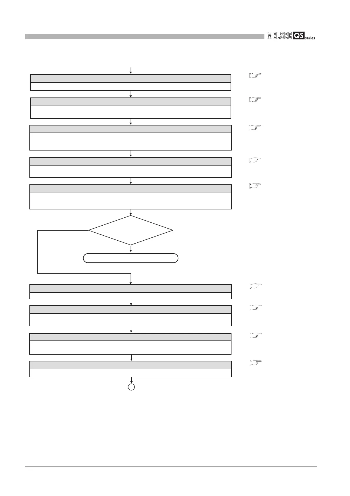
Turn the system power supply OFF and then ON, or perform the reset operation on the
CPU module.
(Continued from the previous page)
Restarting the system
Running the CPU module
Set the RUN/STOP/RESET switch of the CPU module to the RUN position.
Confirm that the "ALIVE" LED and "RUN" LED of the CPU module are on, and the "TEST"
LED is off.
Correct the program?
NO
YES
Stopping the CPU module
Set the RUN/STOP/RESET switch of the CPU module to the STOP position.
Switching to TEST MODE
Switch the mode from SAFETY MODE to TEST MODE by selecting the menu option,
"Switch safety CPU operation mode", in GX Developer.
Confirming the CPU module LEDs
After the operation mode has been switched from SAFETY MODE to TEST MODE using
GX Developer, confirm that both the "TEST" LED and "ALIVE" LED of the CPU module are on.
Correcting the program
Correct the program with GX Developer.
End
After the operation mode has been switched from TEST MODE to SAFETY MODE using
GX Developer, confirm that the "TEST" LED of the CPU module is flashing while the
"ALIVE" LED is on.
Confirming the CPU module LEDs
1
Stopping the CPU module
Set the RUN/STOP/RESET switch of the CPU module to the STOP position.
Switching to SAFETY MODE
Switch the mode from TEST MODE to SAFETY MODE by selecting the menu option,
"Switch safety CPU operation mode", in GX Developer.
• • • CHAPTER 4
• • •
GX Developer Version 8
Operating Manual
(Safety PLC)
• • • CHAPTER 4
• • •
GX Developer Version 8
Operating Manual
• • • CHAPTER 4
• • • CHAPTER 4
• • • CHAPTER 4
• • • CHAPTER 4
• • • GX Developer Version 8
Operating Manual
(Safety PLC)

 Loading...

