10 - 20
10.3 Wiring
10.3.1 The precautions on the wiring
10
LOADING AND INSTALLATION
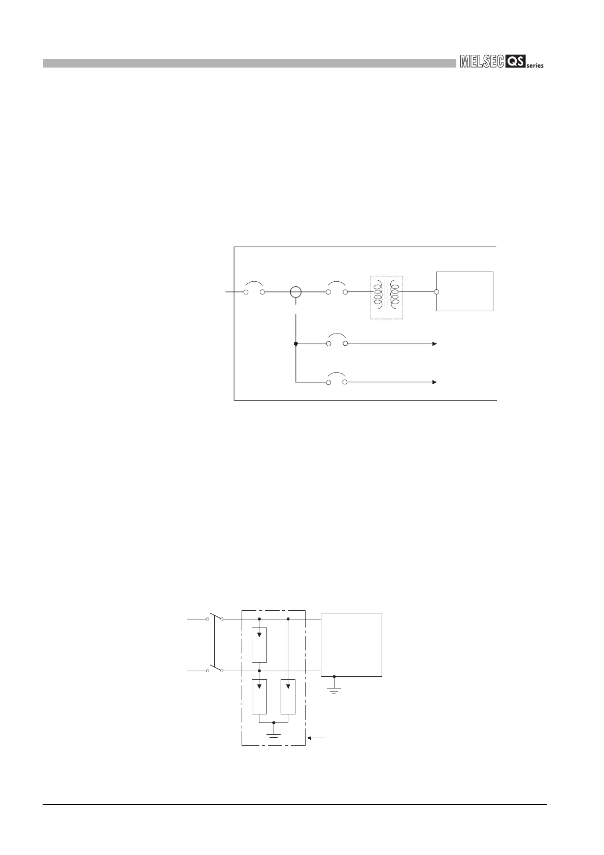
(1) Power supply wiring
• Separate the PLC's power supply line from the lines for I/O devices and power
devices as shown below.
When there is much noise, connect an insulation transformer.
• Taking rated current or inrush current into consideration when wiring the power
supply, be sure to connect a breaker or an external fuse that have proper blown
and detection.
When using a single PLC, a 10A breaker or an external fuse are recommended
for wiring protection.
• 100VAC and 200VAC wires should be twisted as dense as possible.
Connect the modules with the shortest distance.
Also, to reduce the voltage drop to the minimum, use the thickest wires possible
(maximum 2mm
2
).
• Do not bundle the 100VAC and 200VAC wires with, or run them close to, the main
circuit (high voltage, large current) and I/O signal lines (including common line).
Reserve a distance of at least 100 mm from adjacent wires.
• Momentary power failure may be detected or the CPU module may be reset due
to serge caused by lightening.
As measures against serge caused by lightening, connect a surge absorber for
lightening as shown in Figure 10.22.
Using the surge absorber for lightening can reduce the influence of lightening.
Figure 10.21 Power supply connection diagram
Figure 10.22 Connecting a lightning surge absorber
200VAC
T1
Main
power supply
PLC
power supply
Insulation
Transformer
I/O power supply
I/O equipment
On a control panel
Main circuit
power supply
Main circuit equipment
PLC
Relay
terminal block
E1 E1
AC
E1
E2
Surge absorber for lightening
PLC
I/O devices

 Loading...

