Chapter Two: Installation Setu
17
Transducer
Any pressure transducer which delivers at least 0.1 Volt full scale, can be used as the feedback
element for total pressure control (refer to
Optional Equipment
, page 9).
The pressure transducer should be mounted so that it is firmly supported, while at the same time,
isolated from any vibration.
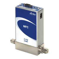
Mass Flow Meters
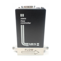
Any mass flow meter (MFM) which delivers at least 5 Volt full scale can be used with the 250
controller depending on the flow rates, types of gas, etc. needed in the control system (refer to
Optional Equipment
, page 9). Refer to the appropriate MFM manual for mounting instructions.
Interconnections
Figures 3 and 4, page 18, show typical piping and cable interconnection diagrams. Figure shows
the usual setup for standard pressure control. Figure 4 shows a setup for multi-gas ratio control.
Connect the valve and sensor to the chamber using short connections with minimum restrictions.
Six inches of ¼” tubing should be maximum. Never reduce the tubing size below that of the
valve and transducer.
Connect the valve and transducer to the back of the controller and set the valve mode switch
(CMAE) to CLOSE (refer to
Rear Panel Controls
, page 26).


 To Next Page