How To Use the Normal/Reverse Switch Cha
ter Four: O
eration
32
How To Use the Normal/Reverse Switch
Most applications will require that when the pressure (or flow) is greater than the set point, the
valve should have less drive to return the process to the proper value. This is “normal” operation
and assumes that the output of the pressure (or flow) transducer
increases
positively for
increasing pressure (or flow).
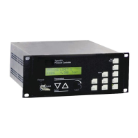
Inside the 250 controller, at approximately the center of the P.C. board, is a slide switch which
can be used to obtain “reverse” action from the controller.
This switch should be in the REVERSE position if either:
•
The pressure (or flow) transducer output
decreases
for increasing pressure (or flow)
•
The valve drive signal
increases
when the pressure (or flow) is greater than the set point
(such as exhaust control)
How To Use External Control
The 250 unit can be externally controlled with two inputs on the Interface connector. Refer to
Table 7, page 22, for the Interface connector pinout.
Note
The front
anel mode switch
must
be in the EXT
osition for the external
inputs to be accepted.
Shorting the CLOSE input (Pin 5) to digital ground (Pin 3) will cause all signals to be removed
from the valve and it will close.
Shorting the MANUAL input (Pin 4) to digital ground (Pin 3) will put the controller in the
Manual mode. Whatever signal dialed into the Manual control, plus bias will be applied to the
valve.
Shorting both the CLOSE and MANUAL inputs to ground will put the controller in Close. If
Pins 4 or 5 are not shorted to Pin 3, the 250 controller will provide automatic control of pressure
(or flow) to the selected set point.


 To Next Page