Chapter Five: Maintenance and Troubleshooting Maintenance
41
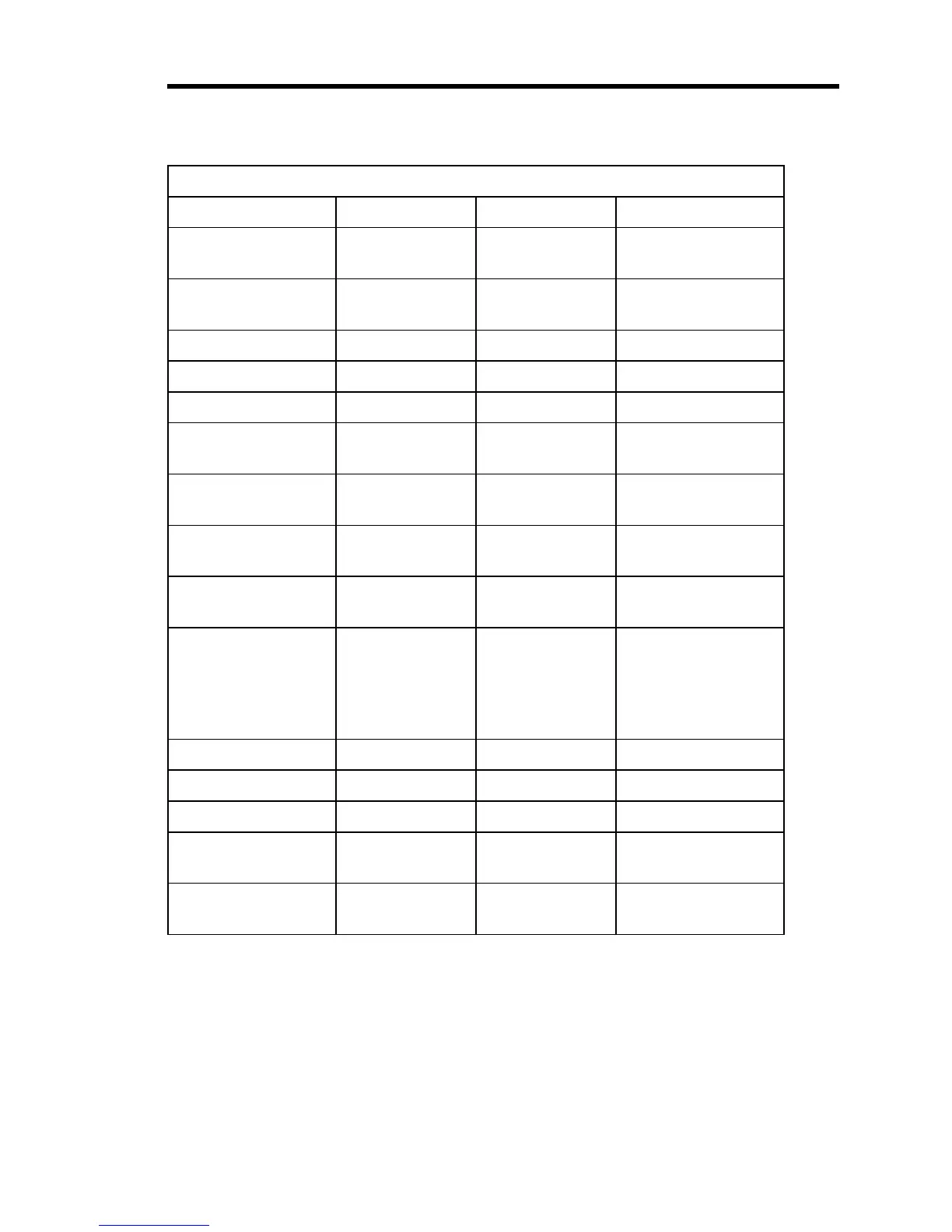
Test Point Voltages
Condition Test Point Voltage Control
(+) 15 V
Supply Jumper
+ 15.00 ±.05 R118
(-) 15 V Supply
Jumper
- 15.00 ±.05 R125
Input = 0.000V TP-6 0.000 Zero (R33)
Input = 0.000V TP-1 0.000 Output Zero (R89)
Set point = 000 TP-11 0.000 S. P. Zero (R89)
Input = 0
Set point = 0
TP-5 0.000 D.A. Zero (R48)
Input = 0
Set point = 0
TP-10 0.000 Error Meter Zero
(R95)
Input = 0
Set point = 0
TP-7 0.000 Lead Zero (R54)
Input = 0
Set point = 0
TP-4 0.000 Gain Zero (R66)
Input = 0
Set point = 0
Mode = AUTO
TP-3 Any voltage
between 0 and
+10 V, but it
should hold
steady
INT Zero (R73)
Input = 10.000V TP-6 5.000 ±.002 SPAN (R41)
Input = 10.000V TP-1 10.000 Signal SPAN (R91)
Setpoint = 1000 TP-11 5.000 ±.002 Setpoint Cal (R19)
TP-6 = TPB-11
(-5.000)
TP-5 0.000 Diff. Amp. Cal.
(R130)
Input = 0
Setpoint = 010
Error Meter 1% Meter Gain (R100)
Table 10: Test Point Voltages


 To Next Page