Chapter Four: Operation How To Use the Multi
le Set Point O
tion
35
Interconnections
The remote set point select lines are brought out on the Interface connector, and are listed in
Table 8. The
digital
ground should be connected to the circuit ground of the digital instrument
that is selecting set points. Refer to Table 7, page 22, for the complete Interface connector
pinout.
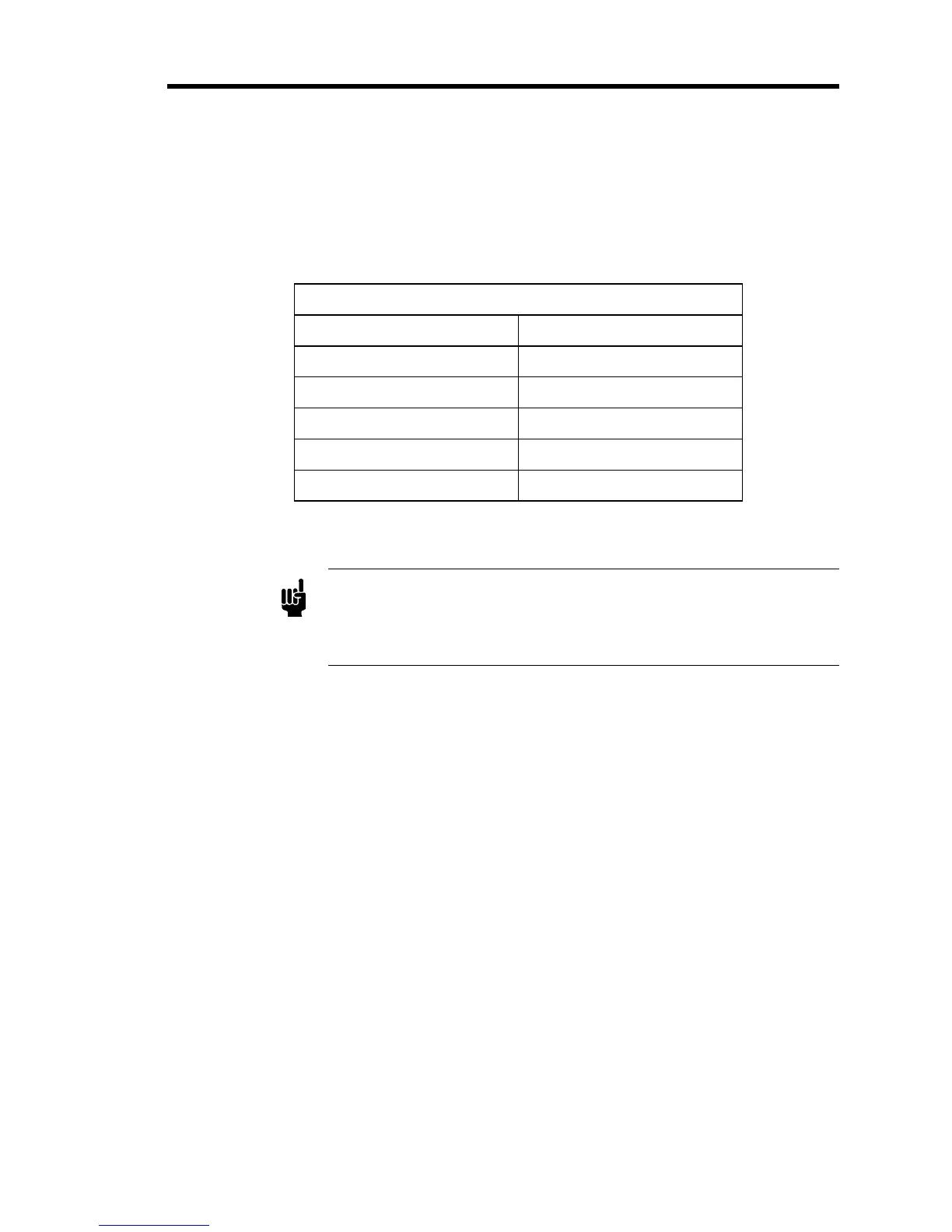
Multiple Set Point Option Pinout
Interface Connector Pin Assignment
3 Digital Ground
6 Set Point 1
7 Set Point 2
9 Set Point 3
10 Set Point 4
Table 8: Multiple Set Point Option Pinout
Note
The External Set Point Si
nal is not a
licable on units with the Multi
le
Set Point Option. Also, the use of Pins 6, 9, and 10 for the MSO
precludes bringing out the Controller Output, Pressure Control Signal,
and D.C. Signal.