Rear Panel Controls Cha
ter Three: Overview
26
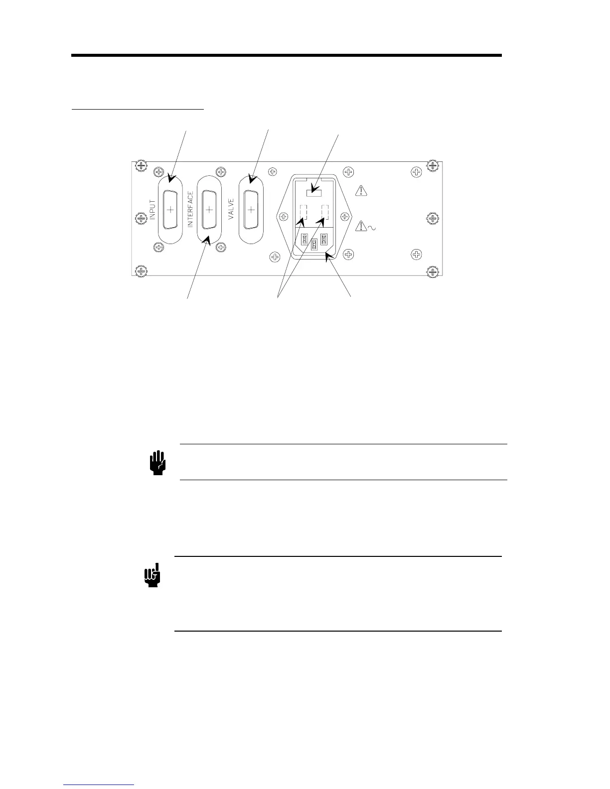
Rear Panel Controls
Input Connector
Interface Connector
Valve Connector
Fuse
Line Cord
Volta
e Selector
100-120V - 0.50A(T)
220-240V - 0.25A(T)
100/115V - 120V
220/230V - 240V
40 VA Max
Valve Output
Max. Voltage
100VDC, 1 mA
Fuses: 250V IEC
Line 50/60 Hz
Figure 6: Rear Panel Controls
LINE CORD
- Provides 115 or 230 VAC to the 250 controller. For protective earthing, plug the
power cord into a properly grounded outlet.
VOLTAGE SELECTOR -
Should be set to the proper input voltage before the line cord is
plugged in and the power turned ON.
FUSE -
Line fuse to protect internal circuitry. Both sides of the line is fused.
Caution
Disconnect line cord from the AC power outlet before replacing the
fuse.
VALVE
- The control valve connects to the 250 controller through a 9-pin female Type “D”
connector. Use cable CB251-2-10 to connect the valve to the controller. Different pins on the
connector are used for various types of valves. The different valve cables are wired to connect to
the proper voltages.
Note
If you are installing the 250E controller into an existing system that uses
the old (hex) connector cables, an adapter cable is required. Use adapter
cable CB250-12-1 or CB250S-12-1 to replace a Type 250A-C controller
with the Type 250E controller. Refer to Table 5, page 20, for the Valve
connector pinout.
INTERFACE
- This 14-pin Amphenol connector provides access to the miscellaneous outputs,
±15V power, and external inputs to the controller. Refer to Table 7, page 22, for the Interface
connector pinout.
INPUT
- This 14-pin Amphenol connector provides ±15V power and accepts the input pressure
signal. Refer to Table 6, page 21, for the Input connector pinout.