Electrical Information Cha
ter Two: Installation
20
Valve Connector
The 9-pin Type “D” connector allows you to connect the 250 unit to a control valve, using cable
CB251-2-10. If you are installing the 250 controller into an existing system that uses the old
(hex) connector cables, an adapter cable is required. Use cable CB250-12-10 or CB250S-12-10
to replace a Type 250A-C controller with the Type 250E controller.
Note
Overall metal braided shielded cables, properly grounded at both ends,
are required during use to meet CE Mark specifications.
Different pins on the connector are used for various types of valves (Piezoelectric or solenoid
type valves). The different valve cables listed in Table 3, page 16, are wired to connect to the
proper voltages.
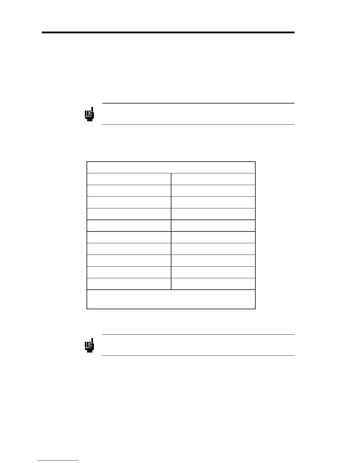
Valve Connector Pinout
Pin Assignment
1* Voltage High
2* Voltage Low (Chassis)
3 Chassis ground
4 No Connection
5 No Connection
6** Current High
7** Current Low
8 No Connection
9 Chassis Ground
* For Piezoelectric type valves
** For solenoid type valves
Table 5: Valve Connector Pinout
Note
The “No Connection” pin assignment refers to a pin with no internal
connection.