Chapter Four: Operation How To Use the Process Limit O
tion
37
Interconnections
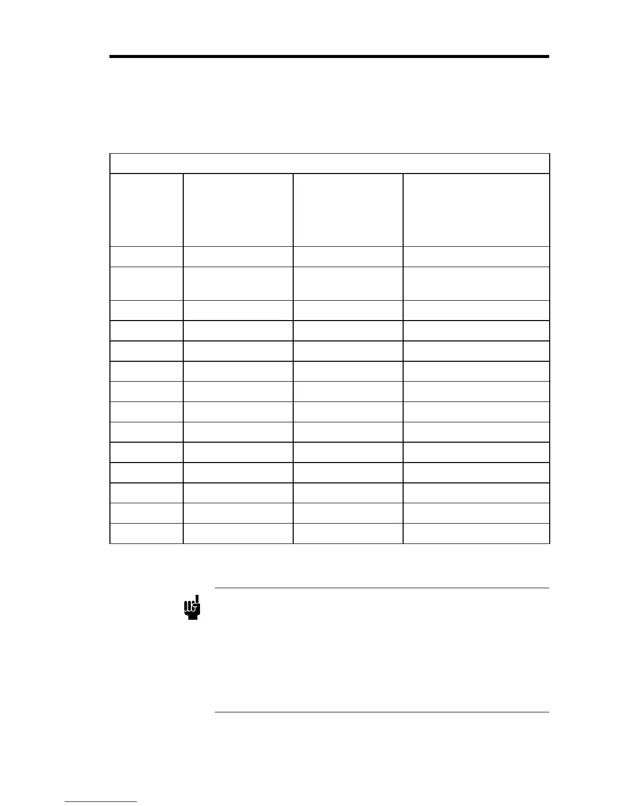
Since there are a limited number of spare pins on the Interface connector, the exact pinout will
depend on which options are installed. Some examples are listed in Table 9.
Process Limit Option Pinout
Interface
Connector
Pin
#1
Standard Unit with
PLO
#2
Multiple Set Point
Option (MSO) and
PLO
#3
MSO, PLO, and Valve
Position Option (VPO)
where valve position
voltage is brought out
1 (+) Ext. Set Point VPO (+10 V)
2 PLO Logic Output
(+5 V)
PLO Logic Output
(+5 V)
PLO Logic Output (+5 V)
3 Digital Ground Digital Ground Digital Ground
4 OPEN OPEN OPEN
5 CLOSE CLOSE CLOSE
6 PLO N.O. Relay Set Point 1 Set Point 1
7 PLO N.C. Relay Set Point 2 Set Point 2
8 (-) Ext. Set Point (-) Ext. Set Point (-) Ext. Set Point
9 PLO Relay Common Set Point 3 Set Point 3
10 -Set Point 4 Set Point 4
11 +15VDC Supply +15VDC Supply +15VDC Supply
12 Power Ground Power Ground Power Ground
13 -15VDC Supply -15VDC Supply -15VDC Supply
14 Chassis Ground Chassis Ground Chassis Ground
Table 9: Process Limit Option Pinout
Note
1.
The N.O. relay contact is CLOSED when the error signal is less than
the Process Limit Set Point (that is, everything is normal). Relay
contacts are rated to switch 0.25 Amps, 28 Volts resistive.
2.
The logic input will source 1 mA (4700 ohms to +5 Volts) and will
sink 10 mA to digital ground.
3.
Digital ground (Pin 3) is the reference for the CLOSE, MANUAL,
and EXTERNAL set point inputs and is also reference for the PLO
output.