Electrical Information Cha
ter Two: Installation
22
Interface Connector
This 14-pin Amphenol connector provides access to the miscellaneous outputs, ±15V power, and
external inputs to the 250 controller. Since there are a limited number of spare pins on the
Interface connector, the exact pinout depends on which options are installed.
•
Refer to Table 8, page 35, for the Multiple Set Point Option pinout
•
Refer to Table 9, page 37, for the Process Limit Option pinout
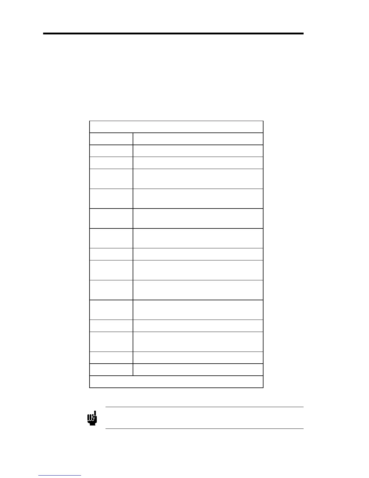
Interface Connector Pinout
Pin Assignment
1 (+) Set Point
2 Reserved
3 Digital Ground
(Common for Manual and Close)
4 Manual
(Connect to Pin 3 to put in Manual)
5Close
(Connect to Pin 3 to put in Close)
6* Controller Output
(0 to 10 Volts - used for pump speed control)
7 Reserved
8 (-) Set Point [Connect to analog ground
(Pin 12) at input source]
9* Pressure Control Signal (PCS)
(10 V full scale)
10* D.C. Signal (0 to 10 Volts)
Duplicate of transducer signal
11 +15V Output
12 Power Supply Ground
(Analog Ground)
13 -15V Output
14 Chassis
*Items are on standard and DVM units.
Table 7: Interface Connector Pinout
Note
The “Reserved”
in assi
nment refers to a
in with an internal connection
which may be assigned a function in the future.