How To Use the Process Limit Option Cha
ter Four: O
eration
36
How To Use the Process Limit Option
The Process Limit Option (PLO) provides a logic signal (+5V) and relay closure when the
controller error deviates from zero by more than the process limit. The process limit can be set
by an internal control to any range from ±0.5 to ±100%. An LED indication is provided on the
board to assist in setup.
The PLO board compares the absolute value of the error signal to the process limit setting. If the
error is less than the setting, the relay is CLOSED, the LED is green, and the logic level is low
(0 Volts). If the error signal is greater than the process limit setting, the relay is OPEN, the LED
is red, and the logic level is high (+5 Volts). If power is lost, the relay will open, the LED will
be off and the logic level will appear high.
Note
For some customers, the logic output is reversed from that described
above;
within
process control gives a high output (+5 Volts) and
out-of-control
gives a low output (0 Volts).
Controls
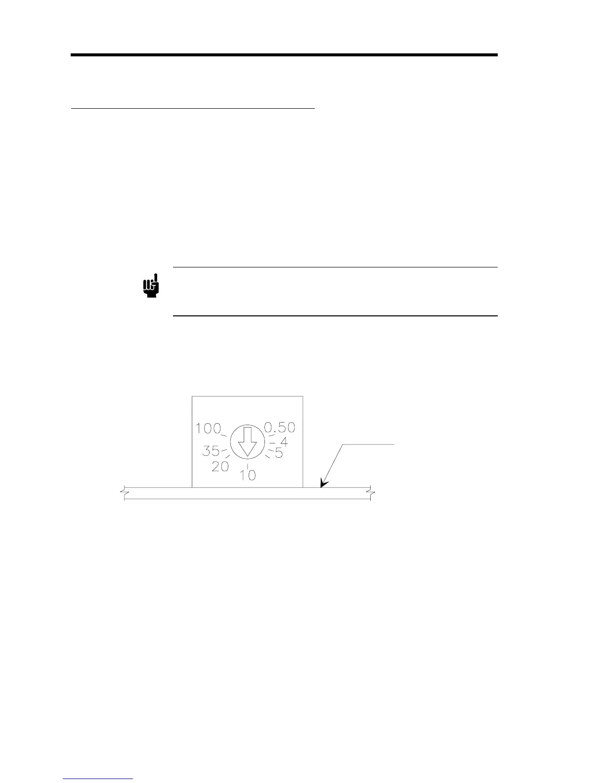
The process limit set point control is a single-turn pot which is non-linear to provide greater
resolution at the lower percentage settings. The approximate settings are shown in Figure 8.
P.C. Board
Figure 8: Process Limit Set Point Control
The PLO is usually shipped with the set points at 10%. However, the process limit set point
should be set as required; 2 to 20% is typically used. Larger percentages will be required for
noisy or fast changing systems.
To establish a precise process limit set point:
1. Input a stable signal (such as zero).
The error meter should read zero (±0.05%) when the controller set point is also at zero.
2. Increase the set point to the deviation at which the PLO is required to trip.
3. Adjust the process limit set point until the LED is just tripping.