Mobileye Proprietary and Confidential
support@mobileye.com
11.
(for cars close as possible to the front bumper and for trucks 1 meter away
from front bumper)
12. Using the image feed (camera installation slide) start gluing the Camera from
the top down, maintaining the Blue and Yellow vertical lines in the scene
ahead as the vertical lines in the image window. When completed, firmly
attach the camera to the windshield.
- The Yellow line indicates the center of the image.
- To see the Red horizontal line you must first fill in the Camera height
measurement.
NOTE: Before attaching the Main Unit verify there is enough room to dismantle the
Main Unit back covers using a small Philips screw driver.
NOTE: For Truck and Bus installations first remove the Mail Unit back covers,
Slide the Camera Down the railing to Level 6 and then follow steps 5 to 12.
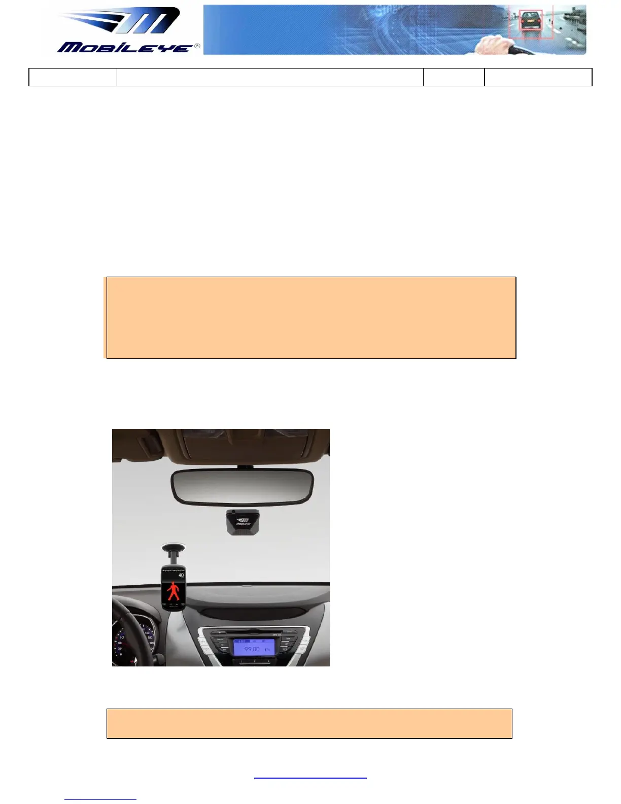
The image below shows the Main Unit (Camera) attached to the front windshield,
typically behind the rear view mirror. The Blue (or Green) L.E.D on the back of the
Main Unit indicates that the Mobileye 6 is receiving power.
Figure 1-10 Vision Sensor Unit located on the windshield behind the rear view mirror
NOTE: At the end of this process, all the system components are connected and all
Mobileye 6 components are attached to the vehicle and connected to the Laptop PC


 To Next Page